6F8C1406 23
4.1 Installation
4
4.1.2 Restrictions
Observe the following restrictions on the installation of optical shared hub units.
• The optical shared hub unit may be used by natural cooling. If it is installed in an
enclosed cabinet, for example, install a fan or other means of cooling to prevent the
inside temperature from rising too high. The working temperature range is 0 to 50
o
C,
but because a power unit is also installed, it is recommended that the temperature be
kept low to extend product life.
• The maximum length of the cable connecting the master hub unit UTNH23A for line A
to the master hub unit UTNH23B for line B is 3 m. In cases where these units for lines
A and B are installed apart from each other, keep the cable within the specified length.
• In principle, install the hub unit UTNH23A for line A and the hub unit UTNH23B for line
B in the same cubicle.
• In case of installing the hub unit UTNH23A for line A and the hub unit UTNH23B for
line B in separate cubicles, attach shielded cables and ferrite cores to them instead of
using the lines A and B connecting cables provided as accessories.
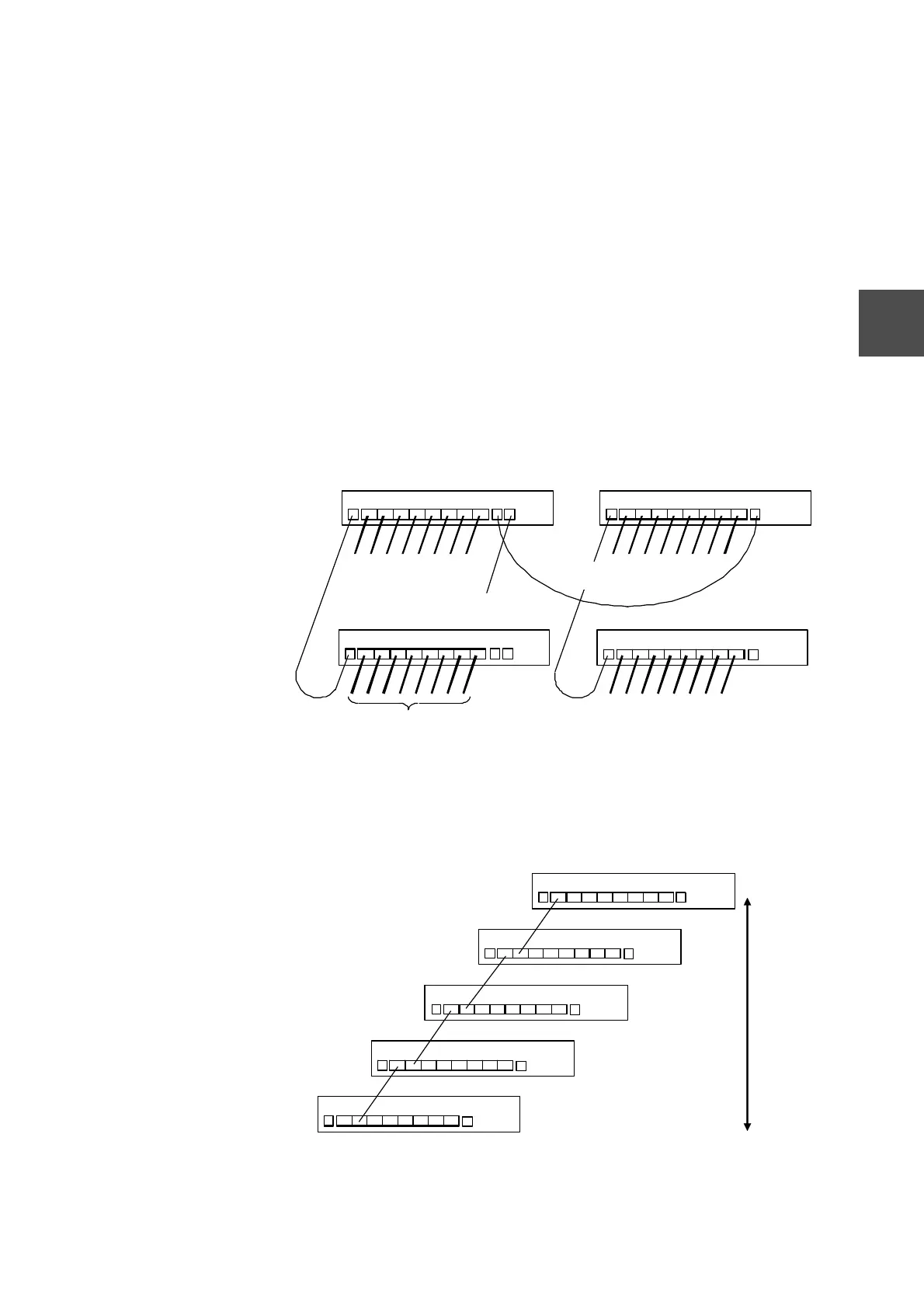
• In installing master hub units for lines A and B one upon another, keep a space of at
least 5 cm from one hub unit to another.
Figure 4-2 Stacking Optical Shared Hub Units
• The maximum steps of cascade connection to hub units is 5.
When use a twisted pair cable to connection, count 1 step.
FX-2 FX- 3 FX-4 FX -5 FX-6 FX -7 FX-8 MEN T
Optical fiber cord with MT
RJ
connector to each station
UTP cable with
modular connector
UTP cable with modular
connector, connectable to only one
ersonal com
uter for maintenance
UTNH23B
DUAL
TX-0 FX- 1 FX-2 FX -3
FX-2 FX- 3 FX-4 FX -5 FX-6 FX -7 FX-8
TX-0
FX-2 FX -3 FX-4 FX-5 FX-6 FX-7 FX-8
When cascading a
hub with a twisted
pair cable, use a
cross cable.
MENTDUAL
DUAL
UTP cross cable with modular connector (SNMP
cable) between master hub units for
lines A and B
T
-0 F
-1 F
-
F
-3 FX
4 FX
FX
6 FX
7 FX
8
TX-0 FX-1 FX-2 FX-3 FX-4 FX-5 FX-6 FX-7 FX -8 DUAL
TX-0 FX -1 FX-2 FX -3 FX-4 FX-5 FX-6 FX-7 FX-8 DU AL
TX-0 FX -1 FX-2 FX-3 FX-4 FX-5 FX-6 FX-7 FX-8 DU AL
TX-0
FX-4 FX- 5 FX- 6 FX- 7 FX-8
DUA
 Loading...