6F8C1406 5
Chapter 2 Names of Parts and
Their Function
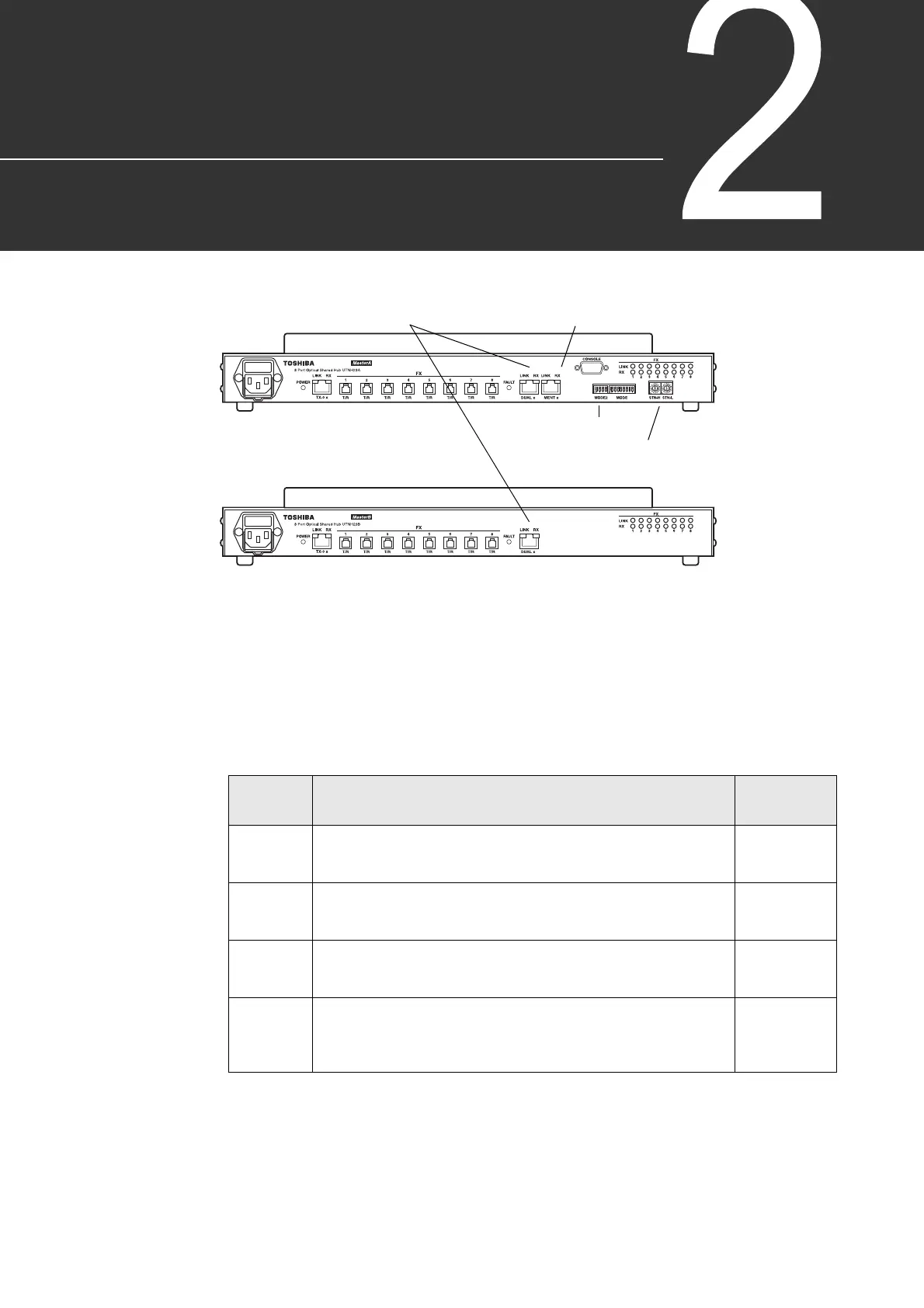
Figure 2-1 shows the front panels of the optical shared hub units and the parts on them.
Figure 2-1 Front Views of Optical Shared Hub Units
The functions of the main parts are shown below.
(1) Status indicating LEDs
These LEDs indicate operating condition, etc. as described in Table 2-1
Status indicating LED
UTNH23A
UTNH23B
SNMP connector (dual) for lines A and B
Ethernet connector (MENT)
Mode setting DIP switches (MODE, MODE2)
Station address setting switches (STN-H/L)
・POWER
・TX-0 LINK
・TX-0 RX
・FAULT
・DUAL LINK
・DUAL RX
・MENT LINK
・MENT RX
・LINK 1-8
・RX 1-8
Table 2-1 Status Indicating LEDs
Name Description
Normal
Indication
PWR
(green)
Power status
ON: Normal
OFF: Power off
ON
LINK
(green)
Link status
ON: Station connected normally to each port
OFF: Station not connected to each port
ON for
connected port
only
RX
(yellow)
Receiving status
ON or blink: Frame being received from each port
OFF: No transmission
ON or blink for
connected port
only
FAULT
(red)
Error status
Blink: Hub repeat function failure
ON: Board failure
OFF: Normal
OFF
 Loading...