E6582062
2-27 2. Installation and wiring
2
3
9
10
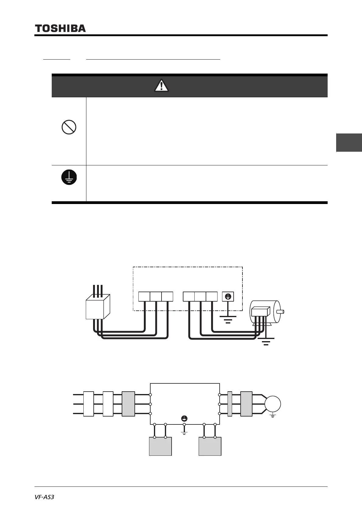
2. 3. 2 Standard connection method
The wiring of the power supply and motor is connected to the power terminal block and the wiring of
external control equipment such as control signals to the control terminal block.
■ Connection to power supply and motor
This diagram shows a standard wiring of the power circuit.
Connection to the power supply and motor wiring is common to all the types.
■ Connection to peripheral devices
This diagram shows an example of connection to peripheral devices.
WARNING
Prohibited
• Do not connect power supply to the output (motor side) terminals [U/T1], [V/T2] and [W/T3].
Connecting power supply to the output will damage the inverter and result in fire.
• Do not insert a braking resistor between DC terminals [PA/+] and [PC/-] or [PO] and[PC/-].
This will result in fire.
Please connect the braking resistor in accordance with the instruction manual.
• Do not touch wires of equipment (e.g. ELCB) that is connected to the inverter power side at
least 15 minutes after turning off the power.
If an electric charge remains in a capacitor in the inverter, touching the wires before the
indicated time will result in electric shock.
Be
grounded
• The grounding wire must be connected securely.
If the grounding wire is not securely connected, when the inverter has failure or earth leakage,
this will result in electric shock or fire.
R/L1
Connect the power supply
to [R/L1], [S/L2], and [T/L3].
Connect the motor to [U/T1],
[V/T2], and [W/T3].
VF-AS3
Molded-case
circuit breaker
or
Earth leakage
circuit breaker
Power supply
E
Motor
S/L2 T/L3 U/T1 V/T2
W/T3
VF-AS3
V/T2
U/T1
W/T3
S/L2
R/L1
T/L3
PBPA
Molded-case
circuit breaker
Note 2)
Magnetic
contactor
Input
reactor
Power
supply
Motor
M
Motor-end surge voltage
suppression filter
Zero-phase
reactor
Note 1) Connect between PA/+ and PC/-
when mounting to a braking unit.
Note 2) Or Earth leakage circuit breaker.
Braking resistor
Note 1)
POPA/+
DC reactor
(frame size A7 and A8
attached in the package)
 Loading...


