E6582062
2-65 2. Installation and wiring
2
3
9
10
■ Occurrence of instability (abnormal vibrations and overcurrent trips)
Unstable phenomena such as abnormal vibrations and overcurrent trips may occur depending on
combinations of the inverter and motor, and load.
1) In the following cases, lower the settings of inverter carrier frequency.
• Combined with a motor that is extremely below applicable motor ratings for the inverter
• Combined with light load with a load factor of 5% or less
• Combined with load whose inertial moment is very small
• Combined with special motors
For details, refer to [6. 14].
2) In the following case, set the S-pattern acceleration/deceleration function (refer to [6.
27. 1]). When vector control is selected, adjust the load
moment of inertia ratio (refer to
[6. 23. 1] or switch to V/f constant mode (refer to [5. 3. 4]).
• Combined with couplings between load devices and motors with high backlash
3) When vector control is selected, adjust the load moment of inertia ratio (refer to [6. 23.
1] or switch to V/f constant control (refer to [5. 3. 4]) in the following case.
• Combined with loads that have sharp fluctuations in rotation such as piston movements
■ Braking motor when turning off power supply
A motor with its power turn off goes into coasting state, and does not stop immediately.
To stop the motor quickly as soon as the power is turn off, install an auxiliary brake. There are
different kinds of brake devices, both electrical and mechanical. Select the brake that is best for the
system.
■ Load that produces regenerative torque
When combined with a load that produces regenerative torque, the overvoltage or overcurrent
protection function may be activated to trip the inverter. Install a braking resistor to deal with it. For
details of the braking resistor, refer to [10. 3. 2].
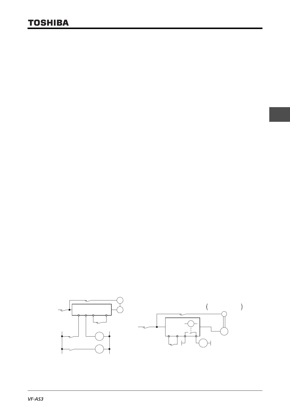
■ Motors with brake
When motors with a brake are directly connected to the inverter's output, the brake cannot be
released at startup because of low voltage. Wire the brake circuit separately from the power circuit.
Circuit diagram 1 Circuit diagram 2
M
MC3
MC2
MC3
MC1
MC2
MC3
MC1
FLB FLC S2(ST)
Power
supply
B
M
MC2
MC2
Non-excitation
activation type brake
MC1
Run/Stop
FCC
R1A R1C
Power
supply
B
RY
 Loading...


