E6581595
L-4
12
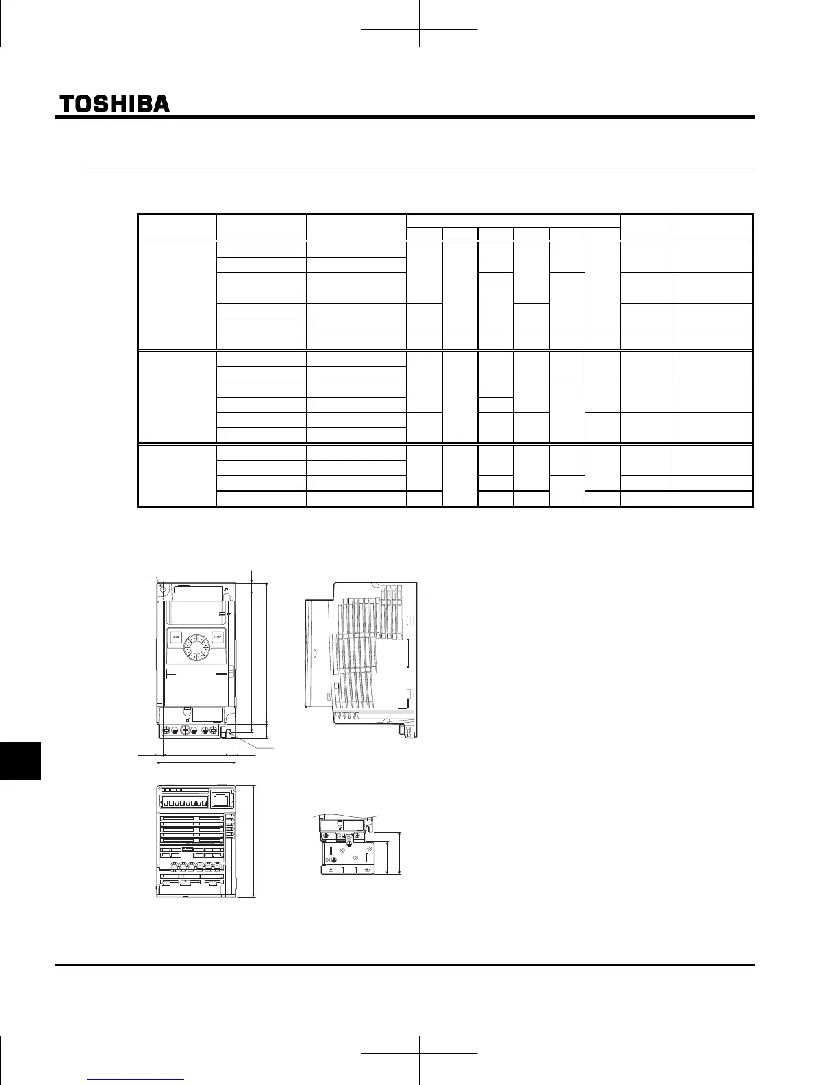
12.2 Outside dimensions and mass
Outside dimensions and mass
Voltage class
Applicable motor
(kW)
Inverter type
Dimensions (mm)
Drawing
Approx. weight
(kg)
W H D W1 H1 H2
3-phase 240V
0.1 VFNC3-2001P
72
130
102
60
131
13
A 0.7
0.2 VFNC3-2002P
0.4 VFNC3-2004P 121
118
B 0.8
0.75 VFNC3-2007P
131
1.5 VFNC3-2015P
105 93 D 1.2
2.2 VFNC3-2022P
4.0 VFNC3-2037P 140 170 141 126 157 14 E 2.0
1-phase 240V
0.1 VFNC3S-2001PL
72
130
102
60
131
13
A 0.7
0.2 VFNC3S-2002PL
0.4 VFNC3S-2004PL 121
118
B 0.8
0.75 VFNC3S-2007PL 131
1.5 VFNC3S-2015PL
105 156 93 12 C 1.5
2.2 VFNC3S-2022PL
1-phase 120V
0.1 VFNC3S-1001P
72
130
102
60
131
13
A 0.7
0.2 VFNC3S-1002P
0.4 VFNC3S-1004P 121
118
B 0.8
0.75 VFNC3S-1007P 105 156 93 12 C 1.3
Outline drawing
φ5
R2.5
72
VF-nC3
EMC plate
(option)
Note2)
W1(Mounting dimension)
H1(Mounting dimension)
H2
130
D
6
5.5
(6.5)
45
58
Note 1. To make it easier to grasp the dimensions of
each inverter, dimensions common to all
inverters in these figures are shown with
numeric values but not with symbols.
Here are the meanings of the symbols used.
W: Width
H: Height
D: Depth
W1: Mounting dimension (horizontal)
H1: Mounting dimension (vertical)
H2: Height of EMC plate mounting area
Note 2. Here are the available EMC plate
Fig.A, B : EMP007Z (Approx. weight : 0.3kg)
Fig.C, D : EMP008Z (Approx. weight : 0.4kg)
Fig.E : EMP009Z (Approx. weight : 0.5kg)
Note 3. The models shown in Fig. A to Fig. D are fixed
at two points: in the upper left and lower right
corners.
Note 4. The model shown in Fig. A, B is not equipped
with a cooling fan.
Note 5. Height measurements in Fig. A do not include
the protuberance for installation.
Fig.A
 Loading...