6-13
FUSES
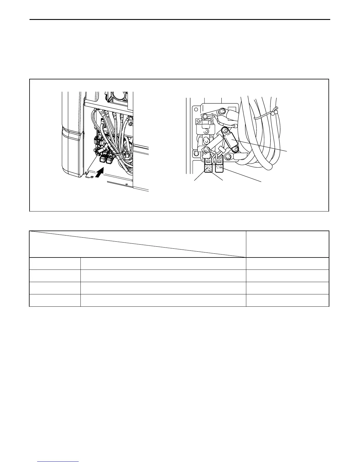
■ Installed positions
Fuses F1 and F4 to F6 are installed in the controller box located under the rear right-hand section of the
vehicle. F1 is of the module type while F4 to F6 are of the blade type. Previously independent F1 for
traveling and F2 for material handling are integrated as F1 fuse for traveling and material handling.
■ Name (Applicable function) and capacity
■ Cautions for fuse replacement
When replacing any fuse, always be sure to disconnect the battery plugs and discharge overall
capacitor by applying a resistance of approx. 100Ω to between P3 and N2.
7FBEF15 to 20
F1 For traveling/material handling 500A
F4 For lights 10A
F5 For control circuit 10A
F6 SAS, for solenoid 10A
F4 F5 F6
F1
A view
A view
 Loading...