9-13
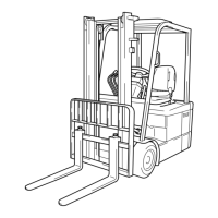
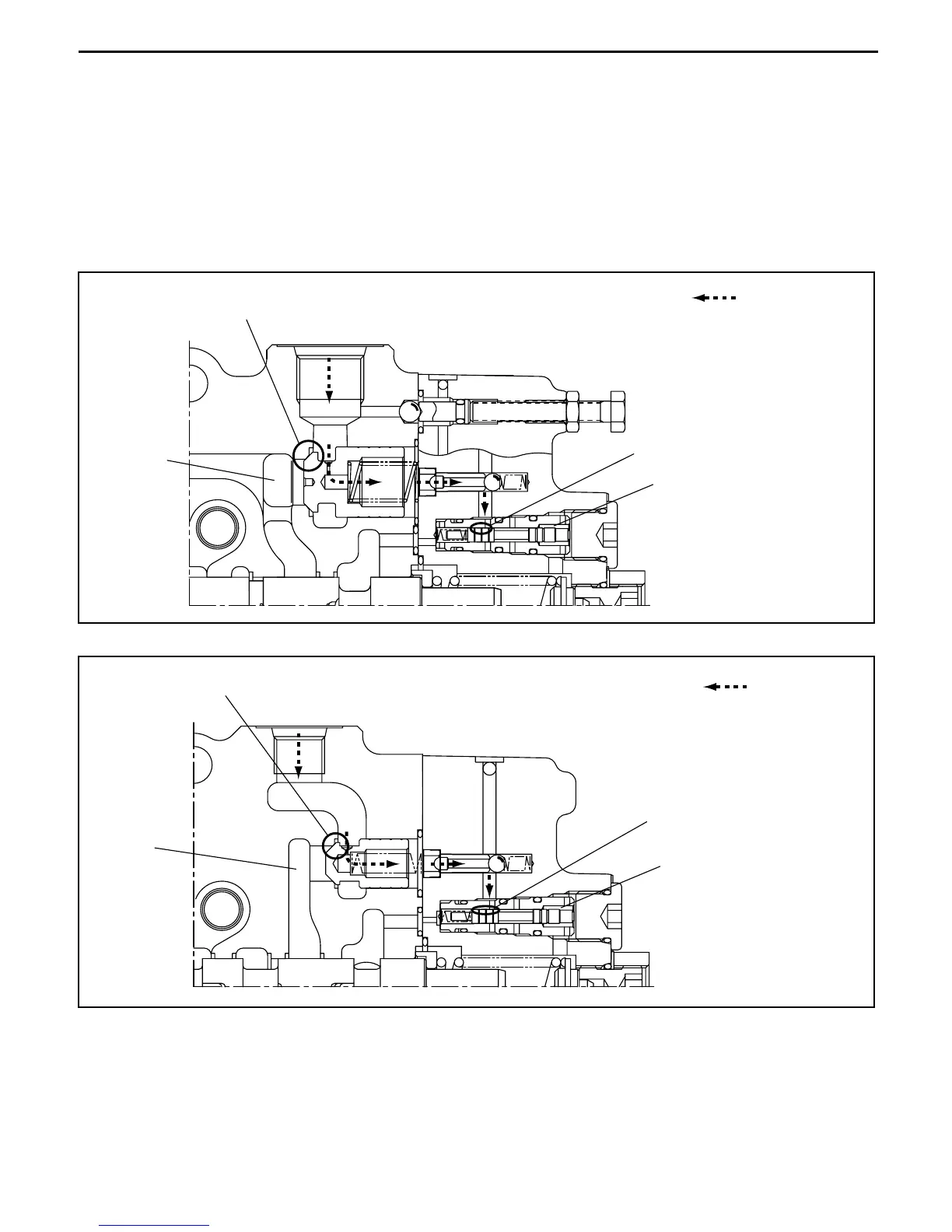
Backpressure leak reduction mechanism
Port C1 of the lift cylinder is connected to the bottom of the lift cylinder, and port C3 of the tilt cylinder is
connected to the rod side of the tilt cylinder.
When load pressure from port C1 and port C3 is applied, leakage to chamber (i) and chamber (j) is
controlled by H and I on the seat.
Leakage of pressure oil that flowed to the lift lock check valve and pressure oil that flowed to the tilt
lock check valve is controlled by land part J and land part K respectively.
This reduces natural drop and natural forward tilt.
Backpressure leak reduction mechanism (sectional view of lift section)
Backpressure leak reduction mechanism (sectional view of tilt section)
J
Tilt lock check valve
H
(i)
Port C1
Pilot flow
I
Port C3
(j)
K
Tilt lock check valve
Pilot flow
 Loading...