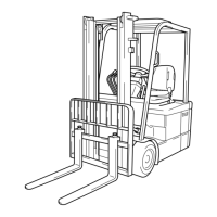
9-17
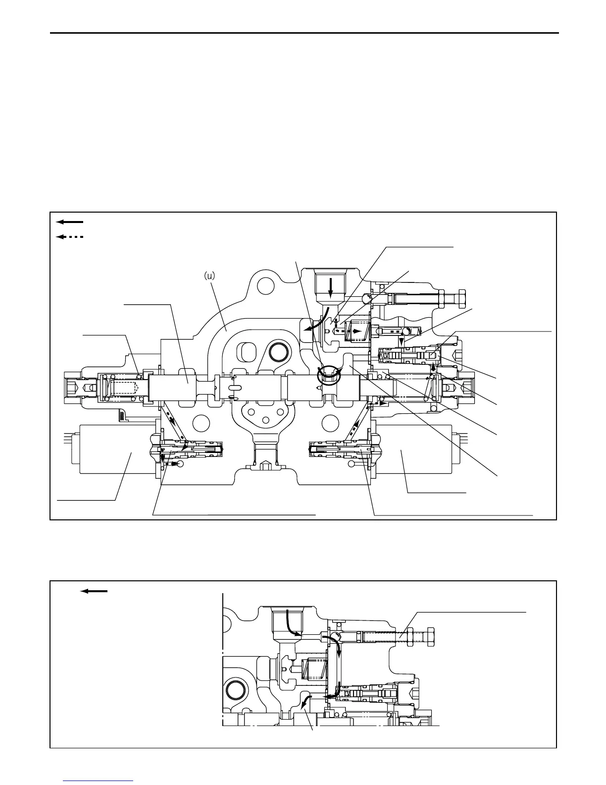
6. Lift DOWN operation
When the lift lever is pushed to the DOWN side, solenoid a1 is energized and the solenoid proportional
valve moves to the left. Then the pressure oil controlled by the pressure reducing valve flows to
chamber (m) on the right side, and the lift spool moves to the left side.
The volume of oil that flows to chamber (m) is proportional to the distance the lever is operated.
The pressure oil from chamber (m) flows through 11 into chamber (o) and shifts the select valve to the
left.
Then the pressure oil operating on port C1 flows through orifice F and enters the select valve.
The circuit is configured with the select valve and chamber (u) connected, so the pressure oil of the
select valve flows through part M and then flows from chamber (g) to the tank.
Accordingly, C1 holding pressure opens the lift lock check valve and the oil flows from C1 to the tank.
Lift DOWN operation (lift section)
If, due to a malfunction, you want to lower the mast without moving the lift spool, opening the
emergency DOWN valve will configure the circuit as shown in the diagram and the mast will descend.
Lift emergency down (lift section)
(o)
11
(m)
5
(g)
M
F
Main flow/excess flow
Pilot flow
Lift logic valve
Logic selection valve
Solenoid a1
Electromagnetic proportional valve
Electromagnetic proportional valve
Solenoid b1
Lift spool
Spring 6
Port C1
Emergency down valve
(g)
Main flow/excess flow
Port C1
 Loading...