7-13
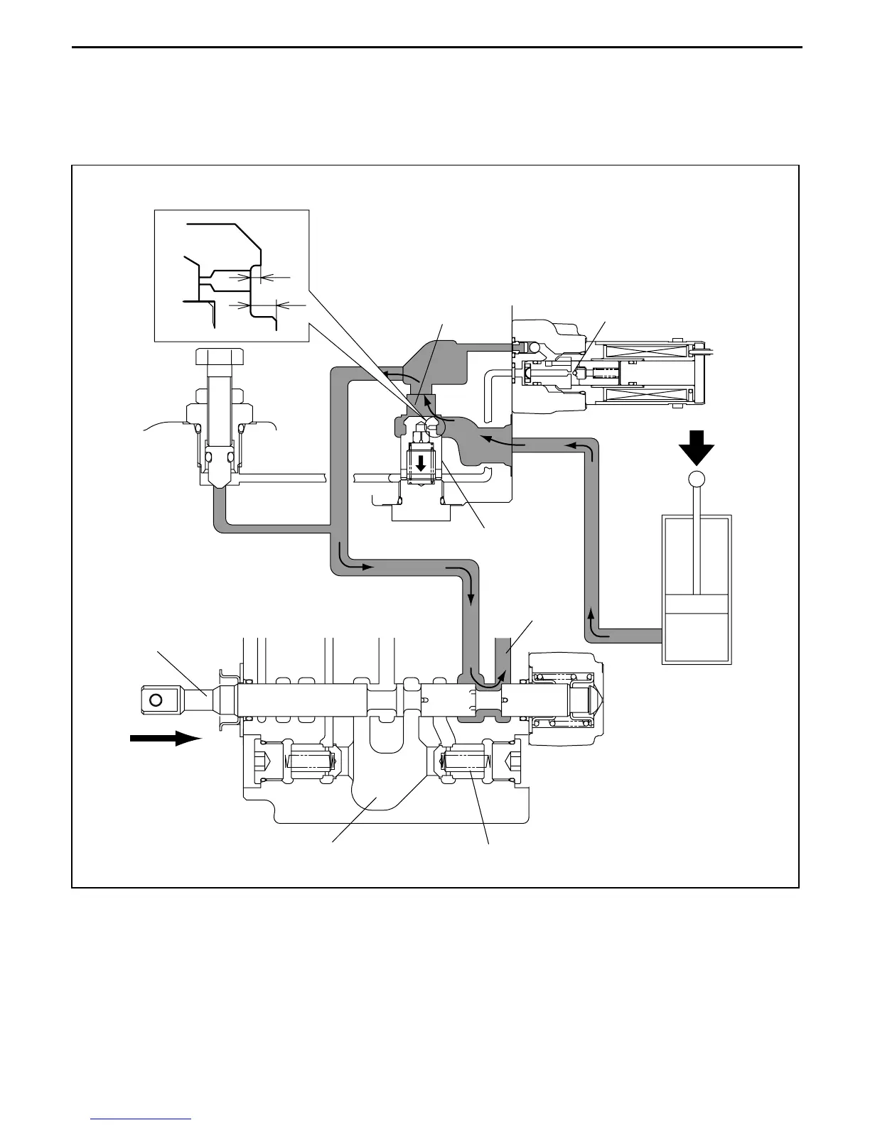
(4) From the result of (2), differential pressure relations stand as follows when the lift lever is operated:
C1 pressure > Logic valve upper side pressure = Logic valve lower side pressure.
(5) Then the C1 port pressure acts on the logic valve to move it downward in the figure because of the
difference in area between a and b of logic valve part A. The pressure opens the logic valve and the
main circuit of the C1 port and the tank port to cause the fork to be lowered.
C1
a
b
Part A
Logic valve upper side
Check valve
Solenoid valve
Lift spool
Logic valve
Tank port
Lift cylinder
Pump port
Lift load check valve
 Loading...