Installation
WSHP-SVX01L-EN 55
Return-Air Duct Panel
Note: The ducted panel design is typically used in
combination with a field installed ceiling filter rack
design.
The return-air arrangement may be easily converted from
a free return-air system, to a ducted return-air system with
the addition of a return-air side panel on the GEH and EXH
unit. By replacing the filter racks with the return-air panel,
a complete seal from the ductwork to the unit is possible.
The 1½ (38 mm) duct flange facilitates ease of field hook-
up to the mechanical system.
Sound Attenuation Pad
For sound-sensitive installations, a vibration pad (field
provided) should be placed beneath the horizontal or
vertical equipment. For the horizontal unit, the pad should
be approximately twice the size of the unit foot print. For
the vertical unit, the pad should be ½ in. (12.7 mm) thick,
and equal to the overall unit foot print.
Hanging the Horizontal Unit
To hang the horizontal configuration (see Figure 53, p. 55):
1. Install the hanging isolators (located in the return-air
section of the unit) into the four hanging brackets.
2. Secure the equipment to a joist, concrete, etc. with the
use of 3/8 in. (9.7 mm) field provided (all-thread) rod.
Each corner should contain field provided nuts and
washers to complete the hanging installation.
3. Slope horizontal units in two directions. The unit
should contain a dual ¼-12 pitch toward the drain
connection. This will insure proper drainage of the
unit. All plumbing to the unit should conform per
national and local codes and is the responsibility of the
contractor.
Table 36. Opening size and part number
GEH/V
Unit Size
(60 Hz)
Unit Size
(50 Hz) A B
Duct Collar Part
Number
006-015 006-012 17½ (445) 13 (330) 4474 1133 0100
018-030 015-024 20½ (521) 16 (406) 4474 5628 0100
036-042 030-036 22½ (572) 17 (432) 4474 1135 0100
048-060 042-060 26½ (673) 19 (483) 4474 1136 0100
EXH Unit
Size
(60 Hz) A B
Duct
Collar
Part
Number
018-024 20½ (521) 16 (406)
4474 5628
0100
030-036 22½ (572) 17 (432)
4474 1135
0100
Note: All dimensions are in inches followed by millimeters in parenthesis.
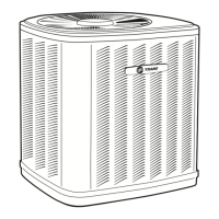
Figure 52. Install return-air duct panel
Install the return-
air duct panel to
the return-air
opening with the
six head screws
provided for the
filter rack
assembly.
DUCT PANEL
with 1 1/2"-FLANGE
A
Unit Side
Unit Side
Unit Top
Unit Top
B
1"
3 3/4"
WARNING
Risk of Unit Dropping!
You MUST mount the unit to an area of the ceiling
strong enough to support the weight of that unit. If
unsure, you MUST confirm with a structural engineer.
Failure to do so could result in unit dropping from the
ceiling which could result in death or serious injury, and
equipment damage.
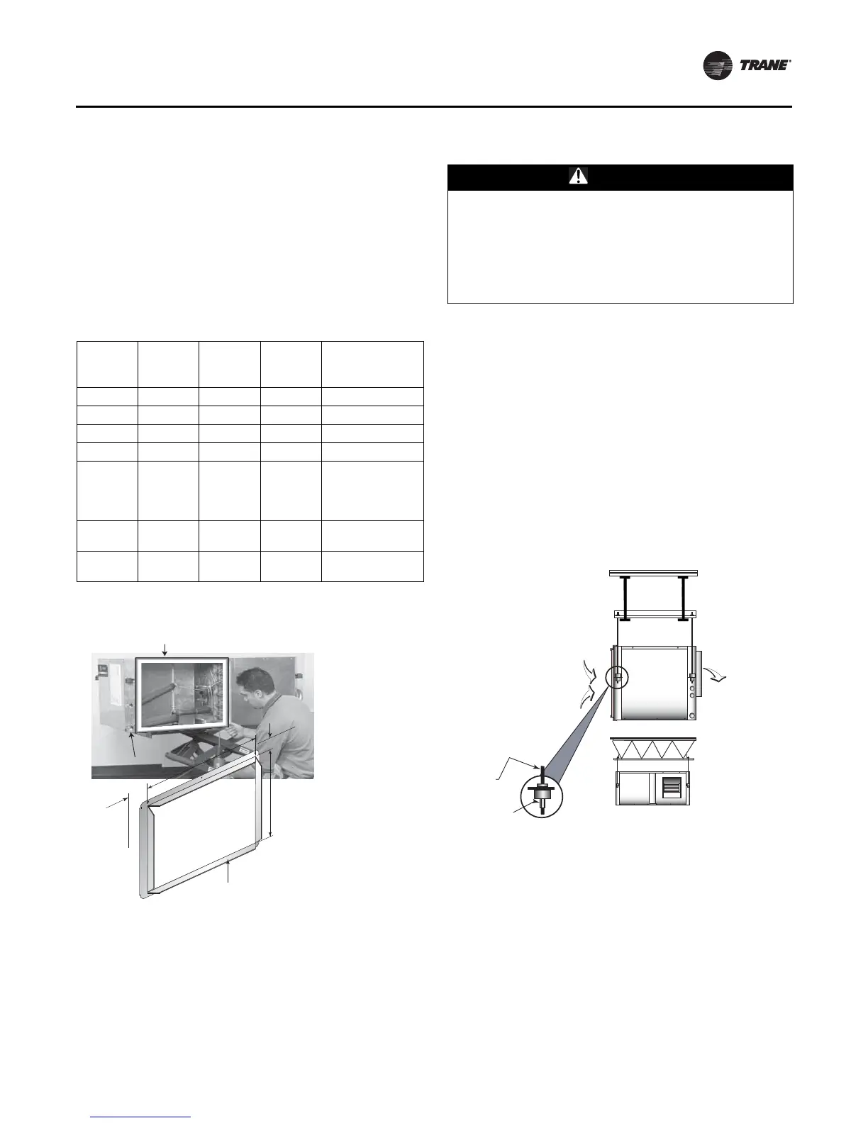
Figure 53. Hanging the unit
SUPPLY-AIR
3/8" ALL-THREAD
(BY OTHERS)
3/8" WASHER / NUT
(BY OTHERS)
RETURN-AIR
 Loading...