Installation
64 WSHP-SVX01L-EN
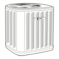
See Figure 76, p. 64.
13. Bundle excess valve wire, and wire tie the bundle
neatly. See Figure 77, p. 64.
14. Install control side service panel.
15. Install the six hanging isolation grommets (see
Figure 78, p. 64) into the hanging brackets The unit
isolators were located in the return-air section of the
unit. See Step 2. Isolators for the economizing package
are located with the economizer.
Note: GEH ½-5 ton and EXH 1½-6 ton.
16. Insulate the economizing piping package and the
supply/return/by-pass hoses (3-hoses) via field
provided pipe insulation. Insulating the piping will stop
condensation from forming on the pipe and dripping
onto the ceiling tiles.
Note: Trane does not provide insulation on the
economizing piping package. This insulation must
be field provided and field installed.
Note: Trane does not provide condensate overflow
protection of the waterside economizer. This must
be field provided and installed.
17. Install filter rack (top and bottom) to the economizing
package. The filter rack is located in the unit’s
packaging along with the filter.
18. Hang unit. See Figure 53, p. 55 for hanging of the
packaged unit. Bottom screws referenced in Step 4
must be installed at this time.
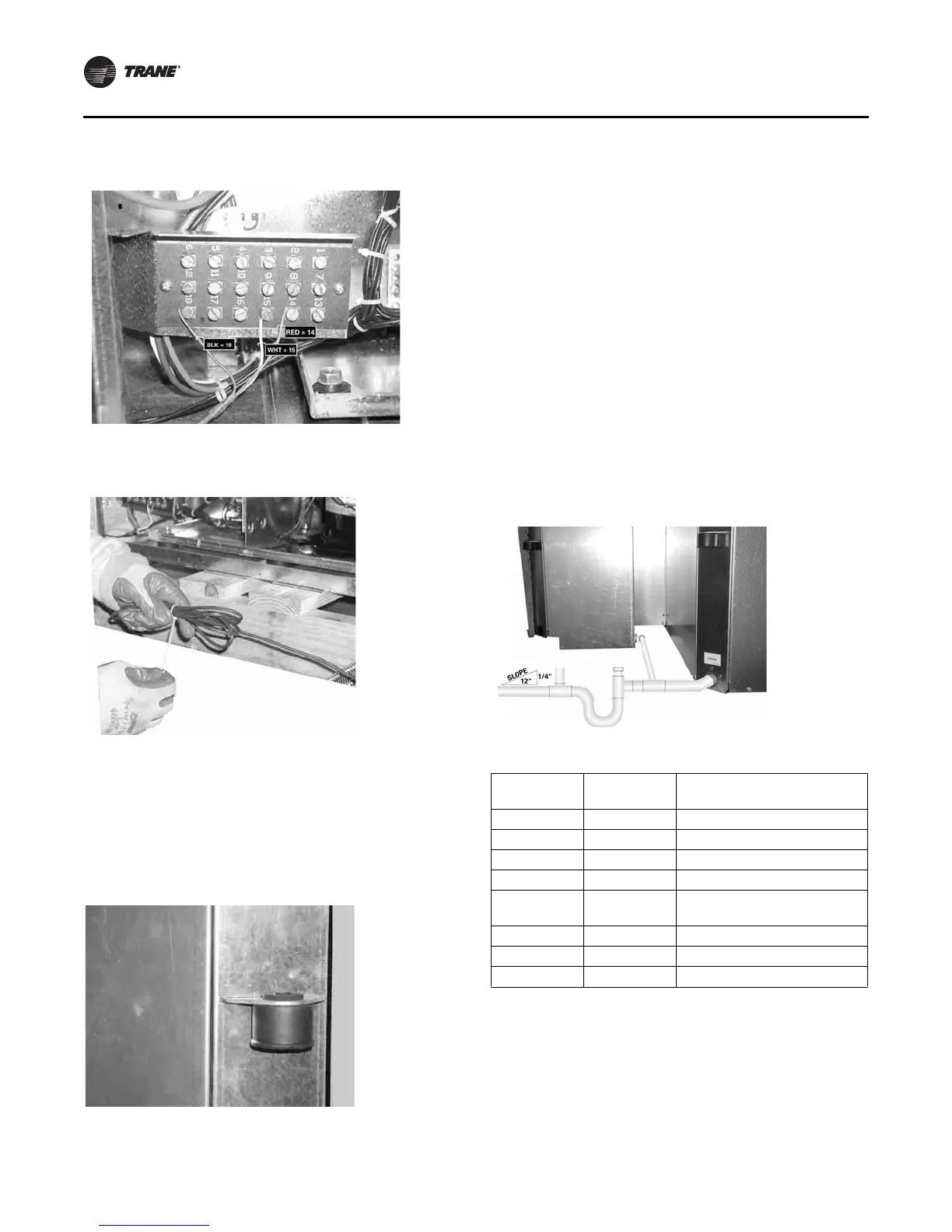
19. Field pipe the drain lines of the waterside economizer
and water-source heat pump together prior to
installing a condensate trap (see
Figure 79, p. 64. See
Figure 54, p. 56 for proper trapping of condensation.
Figure 76. Step 12
Figure 77. Step 13
Figure 78. Step 15
Figure 79. Step 19
Table 41. Economizer part numbers
GEH Unit 60
Hz
GEH Unit 50
Hz
Waterside Economizer Part
Number
006-015 006-012 4474 1690 0100
018-030 015-024 4474 7072 0100
036-042 030-036 4474 1692 0100
048-060 042-060 4474 1693 0100
EXH Unit 60
Hz
GEH Unit 50
Hz
Waterside Economizer Part
Number
018-024 — 4474 7072 0100
030-036 — 4474 1692 0100
042-070 — 4474 1693 0100
 Loading...