SCXF-SVX01Q-EN
37
insulation location. Align plenum front with control
panel side of unit. Using strips and screws provided,
secure plenum to unit. Treat field-cut holes to prevent
fiberglass from entering the air stream.
NNoottee:: Plenum insulation must be applied properly to
prevent air bypass around the plenum. See
Figure 20, p. 37.
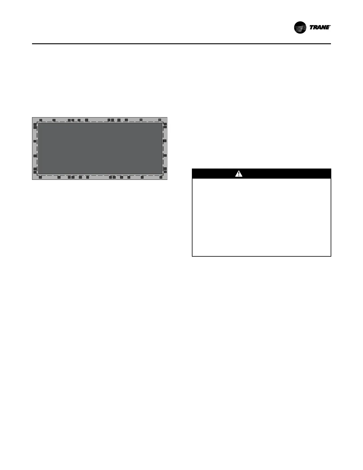
Figure 20. Correct plenum insulation placement
Plenum Bottom View
Dashed line indicates correct insulation placement.
Installing the Airside Economizer
NNoottee:: Airside economizer option available on 20 to 80
tons only.
UUnniitt HHaannddlliinngg
1. Hoist the damper cabinet to the installation location
with straps positioned under the skid as shown in
Figure 21, p. 38. Use spreader bars to prevent unit
damage during lifting.
2. With the damper cabinet at its final location (near
the unit), remove the screws securing it to the skid
from the side flanges. Retain these screws for later
use.
UUnniitt PPrreeppaarraattiioonn
3. Open the access door and remove the damper
cabinet’s support legs and its hanging bracket. The
support legs are secured to the skid, and the
hanging bracket is secured with wire ties to an
inside flange near the cabinet’s base. Remove the
C-channel collar and install it on the unit, if not
already installed.
4. Remove the roll of 1/8" thick gasket from the
damper cabinet’s W-supports, and apply it to the C-
channel collar mounted on the rear of the unit. This
gasket will provide a seal between the damper
cabinet and the unit.
5. Attach the legs (with screws provided) to the leg
brackets located on the damper’s base.
6. Attach a field-provided clevis of suitable strength ( >
1/2"), to each of the corner lifting brackets through
the 7/8" diameter holes.
7. Attach to the clevises a means of lifting the damper
cabinet from its skid.
UUnniitt IInnssttaallllaattiioonn
8. Slowly raise the damper cabinet from its skid.
9. Attach the hanging bracket across the front of the
damper cabinet. Position it with its short flange
pointing to four o’clock, and secure it with screws
provided. See Figure 21, p. 38.
10. Lift the damper cabinet and position it such that the
hanging bracket is positioned over the unit’s C-
channel collar.
11. Lower the damper cabinet until the holes in its side
flanges are aligned with the holes in the C-channel
collar. Install screws removed in step 3 through the
damper cabinet’s side flanges and into the C-
channel’s corresponding holes.
12. Attach ductwork to the top and back dampers
according to local codes.
FFiieelldd WWiirriinngg CCoonnnneeccttiioonnss
WWAARRNNIINNGG
PPrrooppeerr FFiieelldd WWiirriinngg aanndd GGrroouunnddiinngg
RReeqquuiirreedd!!
FFaaiilluurree ttoo ffoollllooww ccooddee ccoouulldd rreessuulltt iinn ddeeaatthh oorr
sseerriioouuss iinnjjuurryy..
AAllll ffiieelldd wwiirriinngg MMUUSSTT bbee ppeerrffoorrmmeedd bbyy qquuaalliiffiieedd
ppeerrssoonnnneell.. IImmpprrooppeerrllyy iinnssttaalllleedd aanndd ggrroouunnddeedd
ffiieelldd wwiirriinngg ppoosseess FFIIRREE aanndd EELLEECCTTRROOCCUUTTIIOONN
hhaazzaarrddss.. TToo aavvooiidd tthheessee hhaazzaarrddss,, yyoouu MMUUSSTT ffoollllooww
rreeqquuiirreemmeennttss ffoorr ffiieelldd wwiirriinngg iinnssttaallllaattiioonn aanndd
ggrroouunnddiinngg aass ddeessccrriibbeedd iinn NNEECC aanndd yyoouurr llooccaall//
ssttaattee//nnaattiioonnaall eelleeccttrriiccaall ccooddeess..
13. Open the damper cabinet’s door and connect the
ffaaccttoorryy--pprroovviiddeedd pplluugg from the actuator to the
ffaaccttoorryy--pprroovviiddeedd pplluugg in the unit’s filter section.
14. CCaabbiinneettss wwiitthh TTRRAAQQ ddaammppeerrss oonnllyy:: Unroll two
rolls of pneumatic tubing located inside damper
cabinet. Route tubes through cabinet’s front upper
panel (0.25 dia. holes provided). Connect to two
pneumatic tubes protruding from customer
electrical connection panel on unit. Be sure to
connect black to black, white stripe to white stripe).
15. CCaabbiinneettss wwiitthh TTRRAAQQ ddaammppeerrss oonnllyy:: Locate the
“bullet” sensor and rolled up wiring in the unit’s
filter section. Route it into the damper cabinet and
insert the sensor into the sensor mounting clip
attached to underside of one of the Traq dampers.
IInnssttaallllaattiioonn -- MMeecchhaanniiccaall

 Loading...


