48
SCXF-SVX01Q-EN
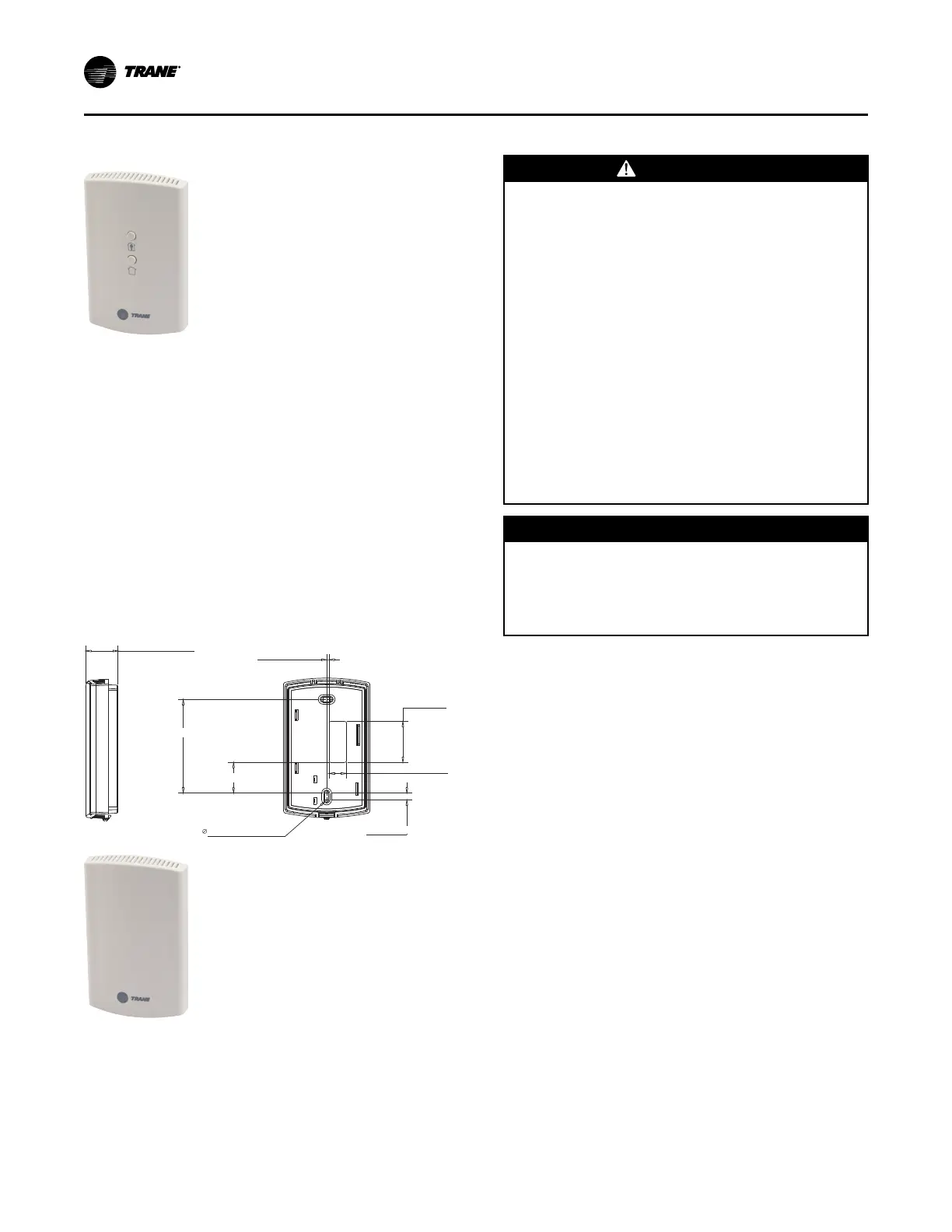
BAYSENS073
Zone temperature sensor with timed override
This electronic analog sensor features single setpoint
capability and timed override with override
cancellation. It is used with a Trane® Integrated
Comfort™ system.
BAYSENS073 features and system control functions
include:
• Remote temperature sensing in the zone
• A timed override button to move an ICS or a
building management system from its
“unoccupied” to “occupied” mode
• Cancel button to cancel the “unoccupied override”
mode
(Possible Schematic Designation: 5U23)
Figure 25. Zone sensor mounting hole locations for:
BAYSENS077
RIGHT BACK
1-3/32 [27,43 mm]
3/32 [2,00 mm]
1-3/8 [35,00 mm]
19/32 [15,00 mm]
15/64 [6,00 mm]
3-5/32 [80,00 mm]
1-1/32 [26,16 mm]
5/32 [3,81 mm] 4X
Zone Sensor Installation
WWAARRNNIINNGG
HHaazzaarrddoouuss VVoollttaaggee ww//CCaappaacciittoorrss!!
FFaaiilluurree ttoo ddiissccoonnnneecctt ppoowweerr aanndd ddiisscchhaarrggee
ccaappaacciittoorrss bbeeffoorree sseerrvviicciinngg ccoouulldd rreessuulltt iinn ddeeaatthh oorr
sseerriioouuss iinnjjuurryy..
DDiissccoonnnneecctt aallll eelleeccttrriicc ppoowweerr,, iinncclluuddiinngg rreemmoottee
ddiissccoonnnneeccttss aanndd ddiisscchhaarrggee aallll mmoottoorr ssttaarrtt//rruunn
ccaappaacciittoorrss bbeeffoorree sseerrvviicciinngg.. FFoollllooww pprrooppeerr
lloocckkoouutt//ttaaggoouutt pprroocceedduurreess ttoo eennssuurree tthhee ppoowweerr
ccaannnnoott bbee iinnaaddvveerrtteennttllyy eenneerrggiizzeedd.. FFoorr vvaarriiaabbllee
ffrreeqquueennccyy ddrriivveess oorr ootthheerr eenneerrggyy ssttoorriinngg
ccoommppoonneennttss pprroovviiddeedd bbyy TTrraannee oorr ootthheerrss,, rreeffeerr ttoo
tthhee aapppprroopprriiaattee mmaannuuffaaccttuurreerr’’ss lliitteerraattuurree ffoorr
aalllloowwaabbllee wwaaiittiinngg ppeerriiooddss ffoorr ddiisscchhaarrggee ooff
ccaappaacciittoorrss.. VVeerriiffyy wwiitthh aa CCAATT IIIIII oorr IIVV vvoollttmmeetteerr
rraatteedd ppeerr NNFFPPAA 7700EE tthhaatt aallll ccaappaacciittoorrss hhaavvee
ddiisscchhaarrggeedd..
FFoorr aaddddiittiioonnaall iinnffoorrmmaattiioonn rreeggaarrddiinngg tthhee ssaaffee
ddiisscchhaarrggee ooff ccaappaacciittoorrss,, sseeee PPRROODD--SSVVBB0066**--EENN..
NNOOTTIICCEE
UUssee CCooppppeerr CCoonndduuccttoorrss OOnnllyy!!
FFaaiilluurree ttoo uussee ccooppppeerr ccoonndduuccttoorrss ccoouulldd rreessuulltt iinn
eeqquuiippmmeenntt ddaammaaggee aass tthhee eeqquuiippmmeenntt wwaass nnoott
ddeessiiggnneedd oorr qquuaalliiffiieedd ttoo aacccceepptt ootthheerr ttyyppeess ooff
ccoonndduuccttoorrss..
NNoottee:: For additional information regarding the safe
discharge of capacitors, see PROD-SVB06
All sensor options ship in the main control panel and
are field installed. Programmable option installation
procedures.
Mounting Location
Mount the sensor on the wall in an area with good air
circulation at an average temperature. Avoid mounting
space temperature sensor is areas subject to the
following conditions:
• Drafts or “dead” spots behind doors or in corners
• Hot or cold air from ducts
• Radiant heat from the sun or appliances
• Concealed pipes and chimneys
• Unheated or non-cooled surfaces behind the
sensor, such as outside walls
• Airflows from adjacent zones or other units
To mount the sensors, remove the dust cover and
mount the base on a flat surface or 2" x 4" junction box.
Sensors ship with mounting screws.
Mounting the Subbase
Remove the zone sensor cover from subbase, and
mount subbase on the wall or on a 2 x 4 junction box.
Route wires through the wire access hole in the
IInnssttaallllaattiioonn -- EElleeccttrriiccaall

 Loading...


