EasyManua.ls Logo

Trane IntelliPak SCWF 20 User Manual

Trane IntelliPak SCWF 20
120 pages
To Next Page IconTo Next Page
To Previous Page IconTo Previous Page
Page #38 background image
38
SCXF-SVX01Q-EN
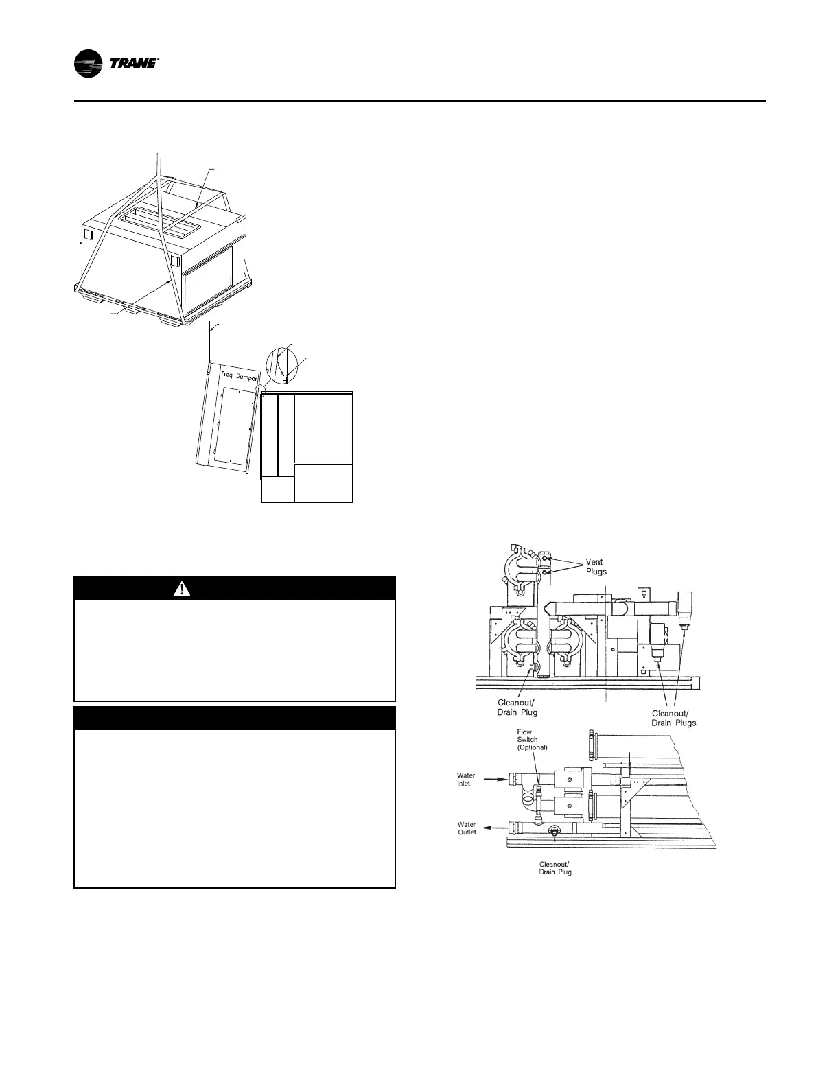
Figure 21. Proper lifting of the airside economizer
(top) and airside economizer option (bottom)
Spreader
Bar
Strap
Lifting
Cable with
spreader bar
C-Channel
Hanging Bracket
Water Piping
Condenser Connections
WWAARRNNIINNGG
HHiigghh PPrreessssuurree WWaatteerr!!
FFaaiilluurree ttoo ffoollllooww iinnssttrruuccttiioonnss bbeellooww ccoouulldd rreessuulltt iinn
ddeeaatthh oorr sseerriioouuss iinnjjuurryy,, aanndd eeqquuiippmmeenntt ddaammaaggee..
PPrroovviiddee rreelliieeff vvaallvvee oonn ssyysstteemm wwaatteerr ppiippiinngg ttoo
pprreevveenntt iinnssttaannttaanneeoouuss rreelleeaassee ooff hhiigghh pprreessssuurree
wwaatteerr..
NNOOTTIICCEE
PPrrooppeerr WWaatteerr TTrreeaattmmeenntt RReeqquuiirreedd!!
TThhee uussee ooff uunnttrreeaatteedd oorr iimmpprrooppeerrllyy ttrreeaatteedd wwaatteerr
ccoouulldd rreessuulltt iinn ssccaalliinngg,, eerroossiioonn,, ccoorrrroossiioonn,, aallggaaee oorr
sslliimmee..
UUssee tthhee sseerrvviicceess ooff aa qquuaalliiffiieedd wwaatteerr ttrreeaattmmeenntt
ssppeecciiaalliisstt ttoo ddeetteerrmmiinnee wwhhaatt wwaatteerr ttrreeaattmmeenntt,, iiff
aannyy,, iiss rreeqquuiirreedd.. TTrraannee aassssuummeess nnoo rreessppoonnssiibbiilliittyy
ffoorr eeqquuiippmmeenntt ffaaiilluurreess wwhhiicchh rreessuulltt ffrroomm uunnttrreeaatteedd
oorr iimmpprrooppeerrllyy ttrreeaatteedd wwaatteerr,, oorr ssaalliinnee oorr bbrraacckkiisshh
wwaatteerr..
Condenser water piping knockouts are in the lower left
end panel. If necessary, remove insulation to gain
access. All field-installed piping must conform to
applicable local, state, and federal codes. To complete
condenser water connections follow the procedure
below.
NNoottee:: Four (4) condenser waterline drain plugs ship in
a bag in the left end of the unit. The installer
must field install these four plugs using pipe
thread sealer. An additional plug is provided for
units with a waterside economizer.
1. Install the vent plugs in the economizer coil headers
and condenser manifolds. See These plugs ship in a
bag with the condenser drain plugs.
2. Attach the water supply line to the inlet connection,
and the return line to the outlet connection.
Entering and leaving water connections for all
condensers are factory manifolded and require only
single connections for entering and leaving water. If
the unit has a waterside economizer and/or control
valves, the factory pipes between these
components.
3. If using a cooling tower, refer to for a typical piping
circuit from the unit.
4. Ensure the water pressure to the unit does not
exceed 400 psig.
NNoottee:: To prevent water pump damage, design system
piping to provide relief when using energy
saving waterside economizer valves.
Figure 22. Economizer coil vent and condenser
cleanout/drain plugs.
Condensate Drain Connections
The condensate drain is internally trapped. Condensate
drain connections are on the right side of the unit.
Connect condensate drain piping to the 1-1/4” NPT
female fitting, using at least 7/8" OD copper or 3/4" OD
iron pipe. Pitch the condensate line downward a
IInnssttaallllaattiioonn -- MMeecchhaanniiccaall

Table of Contents

Questions and Answers:

Trane IntelliPak SCWF 20 Specifications

General IconGeneral
BrandTrane
ModelIntelliPak SCWF 20
CategoryAir Conditioner
LanguageEnglish

Summary

Introduction and Safety

Warnings, Cautions, and Notices

Defines types of safety advisories (WARNING, CAUTION, NOTICE) used throughout the manual.

Proper Field Wiring and Grounding Required!

Emphasizes safety for field wiring and grounding during installation.

Personal Protective Equipment (PPE) Required!

Details required PPE for installation and servicing to prevent hazards.

Follow EHS Policies!

Instructs personnel to follow Environmental, Health, and Safety (EHS) policies for safe work practices.

Overview and Components

Signature Series Self-Contained Unit Components

Describes commercial self-contained units as complete HVAC systems with key features.

Standard Controls

Covers standard controls including the Human Interface (HI) panel and Unit Control Module (UCM).

Optional Controls

Lists optional controls such as disconnect switch, dirty filter switch, and others for unit customization.

Model Number Description

Commercial Self-Contained Signature Series

Explains how to decode the unit model number by interpreting its digits.

Commercial Self-Contained Air-Cooled Condenser

Details the model number description specifically for air-cooled condenser units.

General Data

SCWF/SIWF Water-cooled Data

Provides general data including compressor, evaporator coil, condenser, and fan specifications.

SCRF/SIRF Air-cooled Data

Presents general data for air-cooled units, covering compressor and fan specifications.

Pre-Installation Procedures

Receiving and Inspection

Outlines procedures for receiving units and checking for shipping damage.

Exterior Inspection

Guides on inspecting the unit exterior for damage and verifying nameplate data.

Unit Handling and Protection

Details removal of protective covers and fan isolators for unit preparation.

Dimensional Data

Unit Dimensions

Shows front, back, and top views with dimensions for various unit sizes.

Electrical Connections and Filters

Illustrates electrical connection details and provides filter data and dimensions.

Coils and Economizers

Covers steam, hot water coils, and airside economizer dimensions and data.

Service Clearances

Provides recommended service and code clearances required around the unit.

Weights

Unit Weights

Details unit weights for various models and optional configurations.

Installation - Mechanical

Unit Handling and Rigging

Covers safe procedures for lifting and handling the unit, emphasizing proper rigging.

WARNING Improper Unit Lift!

Warns about the dangers of improper lifting, which can cause serious injury or death.

Piping and Refrigerant System

Covers water piping, refrigerant system, leak testing, and charging procedures.

Hydronic Coil Installation

Guides on installing hydronic coils (steam and hot water) safely.

Installation - Electrical

Power Wiring and Voltage Requirements

Explains power wiring, voltage ranges, and imbalance concerns.

WARNING Hazardous Service Procedures!

Outlines critical safety procedures for electrical servicing.

Static Pressure Transducer Installation

Guides on installing the static pressure transducer for VAV units.

Zone Sensor and Interface Installation

Details installation of zone sensors, remote interfaces, and communication wiring.

Time Clock Installation

Provides instructions for installing and wiring the time clock option.

Operating Principles

Control Sequences of Operation

Outlines control sequences for unit operation, including modes and transitions.

Occupied/Unoccupied Sequences

Explains methods for switching between occupied and unoccupied modes for energy saving.

Cooling Operations

Details cooling sequences, including economizer use, mechanical cooling, and temperature control.

Economizer Operations

Covers airside economizer operation, comparative enthalpy, and damper control.

Controls

Control Modules Overview

Describes the microelectronic control system and its constituent modules.

RTM Module Functions

Explains RTM module capabilities, including inputs, outputs, and alarms.

GBAS Module Functions

Details GBAS module functions for building automation system integration.

Pre-Startup

Startup Checklist

Provides a checklist for verifying installation procedures before unit startup.

Startup

Air-Cooled Unit Startup

Provides specific startup considerations and procedures for air-cooled units.

WARNING Live Electrical Components!

Warns about hazards of working with live electrical components.

Final Refrigerant Charge

Details the procedure for performing the final refrigerant charge accurately.

Startup Procedure

Provides a procedure for establishing nominal startup conditions and recording data.

Maintenance

Service Access

Explains how to access unit controls and components for maintenance.

WARNING Hazardous Voltage w/Capacitors!

Repeats capacitor discharge warnings before servicing any component.

Fan and Belt Maintenance

Covers inspection, cleaning, tensioning, and alignment of fans and belts.

Coil Cleaning

Details procedures for cleaning coil fins, refrigerant coils, and steam/hot water coils.

Periodic Maintenance Checklists

Introduces periodic maintenance checklists, including monthly tasks.

Diagnostics

System Checks and Voltage Imbalance

Details initial system checks and explains voltage imbalance effects.

Potential Unit Issues and Solutions

Lists common unit problems, their causes, and recommended remedies.

Specific Diagnostic Categories

Covers various diagnostic categories like sensor failures, communication issues, and operational limits.

Wiring Diagrams

Published Unit Wiring Diagrams

Lists available unit wiring diagrams by number and description for reference.

Related product manuals