SCXF-SVX01Q-EN
75
Each binary output has a NO and NC contact with a
rating of two amps at 24 Vac. The five binary outputs
are factory preset as shown on the unit wiring diagram
(on the unit control panel door). However, these
outputs can be field defined in a variety of
configurations, assigning single or multiple diagnostics
to any output.
For a complete listing of possible diagnostics, see the
Self-Contained Programming Guide, PKG-SVP01. For
terminal strip locations, refer to the unit wiring diagram
for the GBAS.
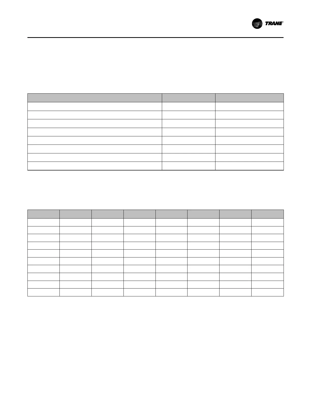
Table 43. GBAS analog input setpoints
Control Parameter
Signal Range Vdc Setpoint Range °F
Occupied zone cooling setpoint (CV units only)
0.5 to 4.5 50 to 90°F
Unoccupied zone cooling setpoint (CV and VAV)
0.5 to 4.5 50 to 90°F
Occupied zone heating setpoint (CV units only)
0.5 to 4.5 50 to 90°F
Unoccupied zone heating setpoint (CV and VAV)
0.5 to 4.5 50 to 90°F
Supply air cooling setpoint (VAV units only)
0.5 to 4.5 40 to 90°F
Supply air hydronic heating setpoint (VAV units only)
0.5 to 4.5 40 to 180 F
Space static pressure setpoint
0.5 to 4.5 0.03 to 0.30 IWC
Supply air pressure setpoint (VAV units only)
0.5 to 4.5 0.0 to 5.0 IWC
Notes:
1. Input voltages less than 0.5 Vdc are considered as 0.5 Vdc input signal is lost, the setpoint will "clamp" to the low end of the setpoint scale. No
diagnostic will result from this condition.
2. Input voltages greater than 4.5 Vdc are considered to be 4.5 Vdc.
3. The actual measured voltage is displayed at the HI.
Table 44. GBAS input voltage corresponding setpoints
Volts
Temp. °F
Volts
Temp. °F
Volts
Temp. °F
Volts
Temp. °F
0.5 50 1.6 60 2.6 70 2.7 80
0.6 51 1.7 61 2.7 71 2.8 81
0.7 52 1.8 62 2.8 72 2.9 82
0.8 53 1.9 63 2.9 73 3.0 83
0.9 54 2.0 64 3.0 74 3.1 84
1.0 55 2.1 65 3.1 75 3.2 85
1.1 56 2.2 66 3.2 76 3.3 86
1.2 57 2.3 67 3.3 77 3.4 87
1.3 58 2.4 68 3.4 78 3.5 88
1.5 59 2.5 69 3.5 79 3.6 89
Input Devices and System Functions
Following are basic input device and system function
descriptions used within the UCM network on self-
contained units. Refer to the unit wiring diagrams for
specific connections.
CCoonnttrroollss

 Loading...


