112
SS-SVX11K-EN
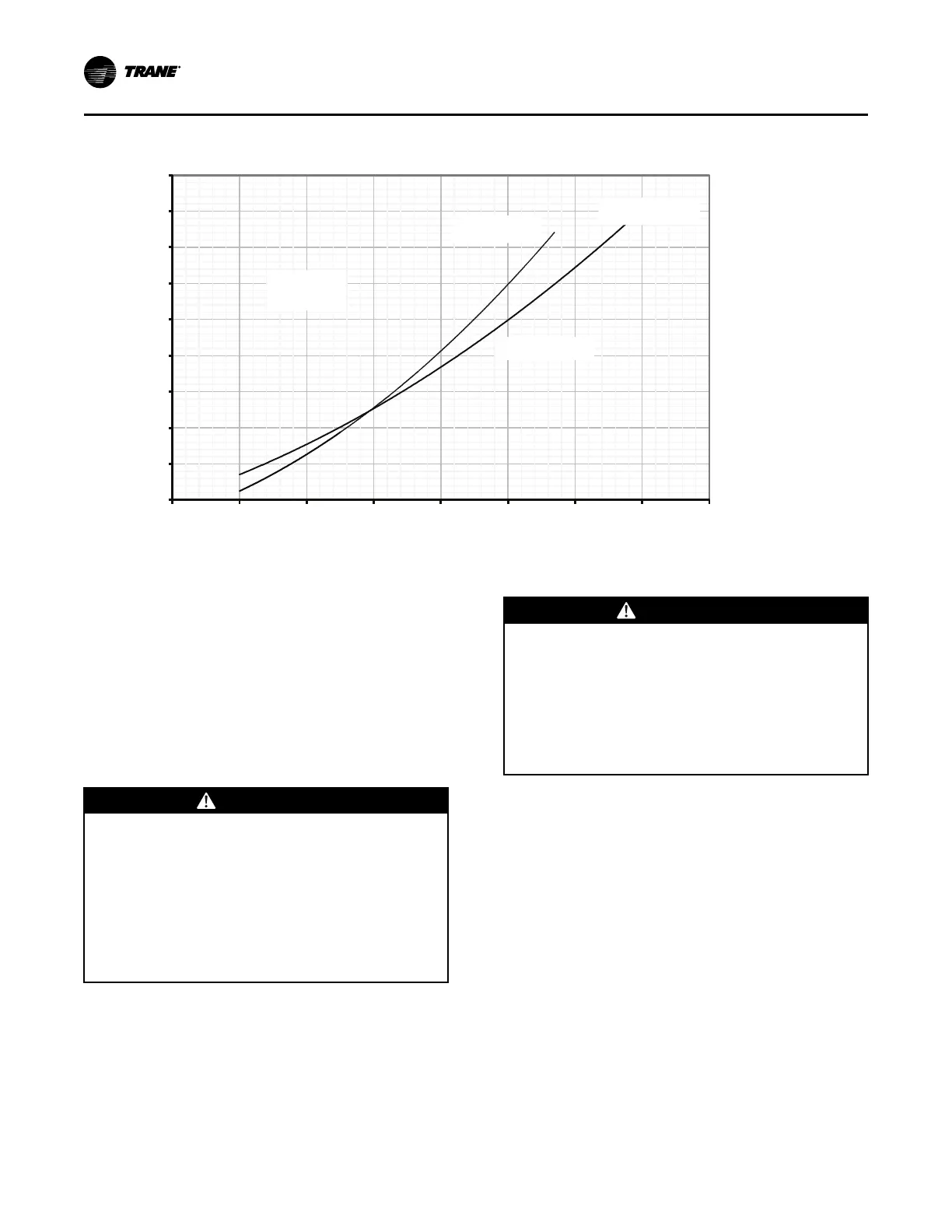
Figure 74. System charging chart (all units)
250
300
350
400
450
500
550
600
650
700
70 80 90 100 110 120 130 140 150
Discharge Pressure, psig
Liquid Line Temp at Outdoor Unit, °F
Remove
Charge
Add Charge
150’ lines
150" lines
Add Charge
50’ lines
Add Charge
Add Charge
Motors Rotating Backward
If, during startup steps above, some or all of the
condenser motors are rotating backward, follow the
steps below.
• If all motors are rotating backward, see All Motors
are Rotating Backward section.
• If some, but not all motors are rotating backward,
see Some Motors are Rotating Backward section.
•
WWAARRNNIINNGG
RRoottaattiinngg CCoommppoonneennttss!!
FFaaiilluurree ttoo ddiissccoonnnneecctt ppoowweerr bbeeffoorree sseerrvviicciinngg ccoouulldd
rreessuulltt iinn rroottaattiinngg ccoommppoonneennttss ccuuttttiinngg aanndd ssllaasshhiinngg
tteecchhnniicciiaann wwhhiicchh ccoouulldd rreessuulltt iinn ddeeaatthh oorr sseerriioouuss
iinnjjuurryy..
DDiissccoonnnneecctt aallll eelleeccttrriicc ppoowweerr,, iinncclluuddiinngg rreemmoottee
ddiissccoonnnneeccttss bbeeffoorree sseerrvviicciinngg.. FFoollllooww pprrooppeerr
lloocckkoouutt//ttaaggoouutt pprroocceedduurreess ttoo eennssuurree tthhee ppoowweerr
ccaann nnoott bbee iinnaaddvveerrtteennttllyy eenneerrggiizzeedd..
WWAARRNNIINNGG
HHaazzaarrddoouuss VVoollttaaggee!!
FFaaiilluurree ttoo ddiissccoonnnneecctt ppoowweerr bbeeffoorree sseerrvviicciinngg ccoouulldd
rreessuulltt iinn ddeeaatthh oorr sseerriioouuss iinnjjuurryy..
DDiissccoonnnneecctt aallll eelleeccttrriicc ppoowweerr,, iinncclluuddiinngg rreemmoottee
ddiissccoonnnneeccttss bbeeffoorree sseerrvviicciinngg.. FFoollllooww pprrooppeerr
lloocckkoouutt//ttaaggoouutt pprroocceedduurreess ttoo eennssuurree tthhee ppoowweerr
ccaann nnoott bbee iinnaaddvveerrtteennttllyy eenneerrggiizzeedd.. VVeerriiffyy tthhaatt nnoo
ppoowweerr iiss pprreesseenntt wwiitthh aa vvoollttmmeetteerr..
All Motors are Rotating Backward
1. Turn the field supplied disconnect switch or circuit
protector switch that provides power to the
condensing unit to the “Off” position. Lock the
disconnect switch in the open position while
working at the unit.
2. Verify that field connected main power phase
sequence matches that specified on the unit wiring
diagrams. Rotation will be incorrect if any two
power wires are interchanged at the unit terminal
block 1TB1 or the optional factory mounted non-
fused disconnect switch (1S1) in the unit control
panel.
3. Check the unit phase module (1U1) for correct
operation and unit wiring.
SSttaarrtt--UUpp

 Loading...