96
SS-SVX11K-EN
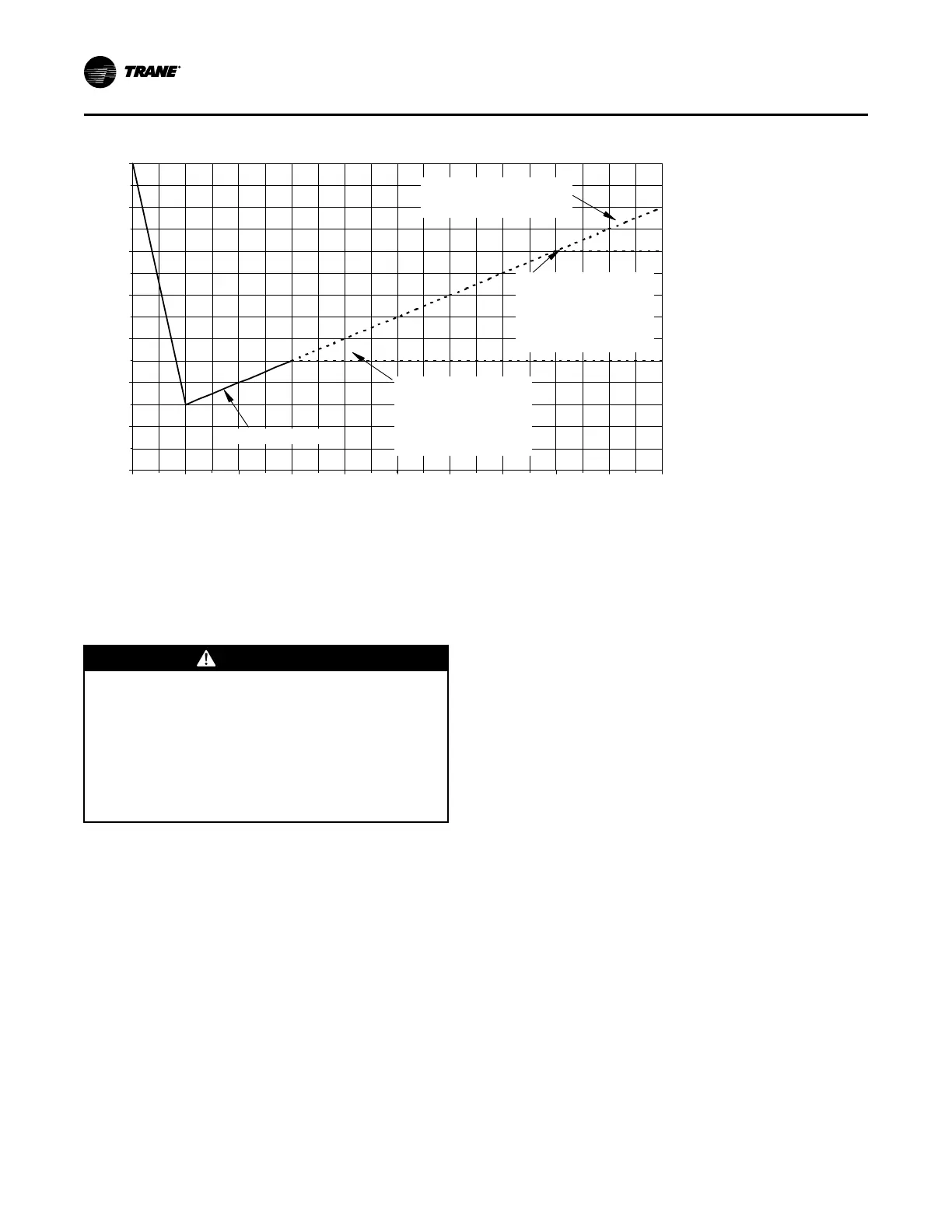
Figure 68. Evacuation time vs. pressure rise
200
400
600
800
1000
1200
1400
1600
TIME IN MINUTES
PRESSURE IN MICRONS
Continuously increasing pressure
indicates the presence of leaks,
moisture or both.
Initial evacuation pressure
State of equilibrium indicates the
true amount of moisture left in
the system. It indicates that no
leaks are present and the
system is properly evacuated
State of equilibrium indicates
the true amount of moisture
left in the system. It indicates
that no leaks are present, but
further evacuation is required.
-10
0 10 20 30 40 50 60 70 80 90
Discharge Air Controller
Checkout (Honeywell W7100A)
NNoottee:: The following checkout procedure must be
performed in its entirety and in the sequence
given.
WWAARRNNIINNGG
HHaazzaarrddoouuss VVoollttaaggee!!
FFaaiilluurree ttoo ddiissccoonnnneecctt ppoowweerr bbeeffoorree sseerrvviicciinngg ccoouulldd
rreessuulltt iinn ddeeaatthh oorr sseerriioouuss iinnjjuurryy..
DDiissccoonnnneecctt aallll eelleeccttrriicc ppoowweerr,, iinncclluuddiinngg rreemmoottee
ddiissccoonnnneeccttss bbeeffoorree sseerrvviicciinngg.. FFoollllooww pprrooppeerr
lloocckkoouutt//ttaaggoouutt pprroocceedduurreess ttoo eennssuurree tthhee ppoowweerr
ccaann nnoott bbee iinnaaddvveerrtteennttllyy eenneerrggiizzeedd.. VVeerriiffyy tthhaatt nnoo
ppoowweerr iiss pprreesseenntt wwiitthh aa vvoollttmmeetteerr..
The W7100A (7U11) discharge air controller can be
checked out using a highly accurate digital volt-
ohmmeter and the W7100A accessory tool kit (Trane
part # TOL-0101 or Honeywell part # 4074EDJ).
1. Turn all control switches to the “OFF” position to
deactivate the Evaporator Fan and the Mechanical
Cooling.
2. Turn the main power disconnect switch for the
evaporator fan and condensing unit “OFF”.
3. Disable the mechanical cooling by removing the
field installed evaporator fan auxiliary interlock wire
from terminal board 7TB5 terminal 3 inside the unit
control panel.
4. At the Discharge Air Controller, in the unit control
panel, remove the red dust cover from the test plug
socket at the bottom of the W7100A. Insert the
“Test Plug”, from the kit, into the test plug socket.
The test plug overrides most of the built-in time
delays for staging the compressors “On” and “Off”.
Refer to the illustration in Figure 69, p. 98 for
terminal and control dial identification.
5. Install a jumper across the P and P1 terminals
(remote setpoint input), and another jumper across
terminals 6 and 7 (reset input) if reset is enabled.
6. Disconnect the wires from terminals T and T1
(discharge air sensor).
7. Remove the 3,400 ohm resistor (blue leads) from
the test kit and connect it across terminals T and T1
to simulate a discharge air temperature of 60°F.
8. Set the “Setpoint F” dial at 56°F or below; then set
the “Control Band F” dial at 2 to minimize the
control response time.
9. At the Discharge Air controller, verify that the
controller ground wire is connected to the chassis
ground. Refer to the unit wiring diagram that
shipped on the unit.
NNoottee:: It is not necessary to set the “Reset F” dial
since the factory installed jumper across
Terminals 6 and 7 disables this dial.
10. Turn the control circuit switch 1S2, in the unit
control panel, and the main power disconnect
switch for the condensing unit to the “ON”
position.
After approximately 2 minutes (time required to
drive the economizer fully open), the LEDs on the
W7100 should begin to illuminate as the cooling
outputs stage “On”.
PPrree--SSttaarrtt

 Loading...