116
SS-SVX11K-EN
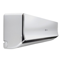
Figure 82. 100 Ton cooling cycle pressure curve
105°F OD
95°F OD
85°F OD
75°F OD
65°F OD
Suction pressure, PSIG
95 105 115 125 135 145
250
300
350
400
450
500
550
Discharge pressure, PSIG
100T Cooling Cycle Pressure Curve
All compressors and condenser fans running
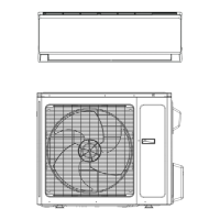
Figure 83. 120 Ton cooling cycle pressure curve
105°F OD
95°F OD
85°F OD
75°F OD
65°F OD
Suction pressure, PSIG
95 105 115 125 135 145
250
300
350
400
450
500
550
Discharge pressure, PSIG
120T Cooling Cycle Pressure Curve
All compressors and condenser fans running
Final System Setup
WWAARRNNIINNGG
HHaazzaarrddoouuss VVoollttaaggee!!
FFaaiilluurree ttoo ddiissccoonnnneecctt ppoowweerr bbeeffoorree sseerrvviicciinngg ccoouulldd
rreessuulltt iinn ddeeaatthh oorr sseerriioouuss iinnjjuurryy..
DDiissccoonnnneecctt aallll eelleeccttrriicc ppoowweerr,, iinncclluuddiinngg rreemmoottee
ddiissccoonnnneeccttss bbeeffoorree sseerrvviicciinngg.. FFoollllooww pprrooppeerr
lloocckkoouutt//ttaaggoouutt pprroocceedduurreess ttoo eennssuurree tthhee ppoowweerr
ccaann nnoott bbee iinnaaddvveerrtteennttllyy eenneerrggiizzeedd.. VVeerriiffyy tthhaatt nnoo
ppoowweerr iiss pprreesseenntt wwiitthh aa vvoollttmmeetteerr..
After completing the Pre-start and Start-up procedures
outlined in the previous sections, perform these final
checks before leaving the unit:
• Turn the 115 volt control circuit switch 1S2 “Off”
and program the Night Setback (NSB) panel (if
applicable) for proper unoccupied operation. Refer
to the programming instructions for the specific
panel.
• Verify “System” selection switch and the “Fan
Mode” selection switch at the Remote panel is set
correctly.
• Verify that the “System” control switch for the
supply fan is “On”.
• Verify that the “System” control switch for the
supply fan or the chilled water pump is “On.”
• Set the correct “Operating Temperature” for the
system at the system controller. Refer to Minimum
Starting Ambient Temperature table for the
recommended control set points for the appropriate
control option.
• Turn the 115 volt control circuit switch 1S2 “On”.
The system will start automatically once a request
for cooling has been given.
• Verify that all exterior panels and the control panel
doors are secured in place.
Table 38. Recommended operating setpoints, 20 to 120 ton units
Control
Control Setting Recommended Setting
Discharge Air Controller
(VAV units only)
Supply Air Setpoint Set at design discharge (supply) air temperature; minimum setting = 55° F
Reset Setpoint Set at maximum amount of allowable reset for supply air setpoint.
Control Band
Set at 6°F Minimum Setpoint
Chiller Control
(EVP units only)
Freezestat
Leaving Fluid Setpoint Set at design leaving chilled water temperature (typically) 44° F
Reset Setpoint Set at maximum amount of allowable reset for leaving fluid setpoint.
Control Band
Set at 6° F Minimum Setpoint (minimum control temperature cannot be
lower than freezestat setting)
Freezestat
Low Limit Solution
Temperature
Set at 5° F Minimum above the Chilled Solution Freeze Temperature
Zone Thermostat
(CV units only)
Zone Setpoint Set at desired space temperature.
Note: For "No Controls" Units, see System Engineer
SSttaarrtt--UUpp

 Loading...