SS-SVX11K-EN
45
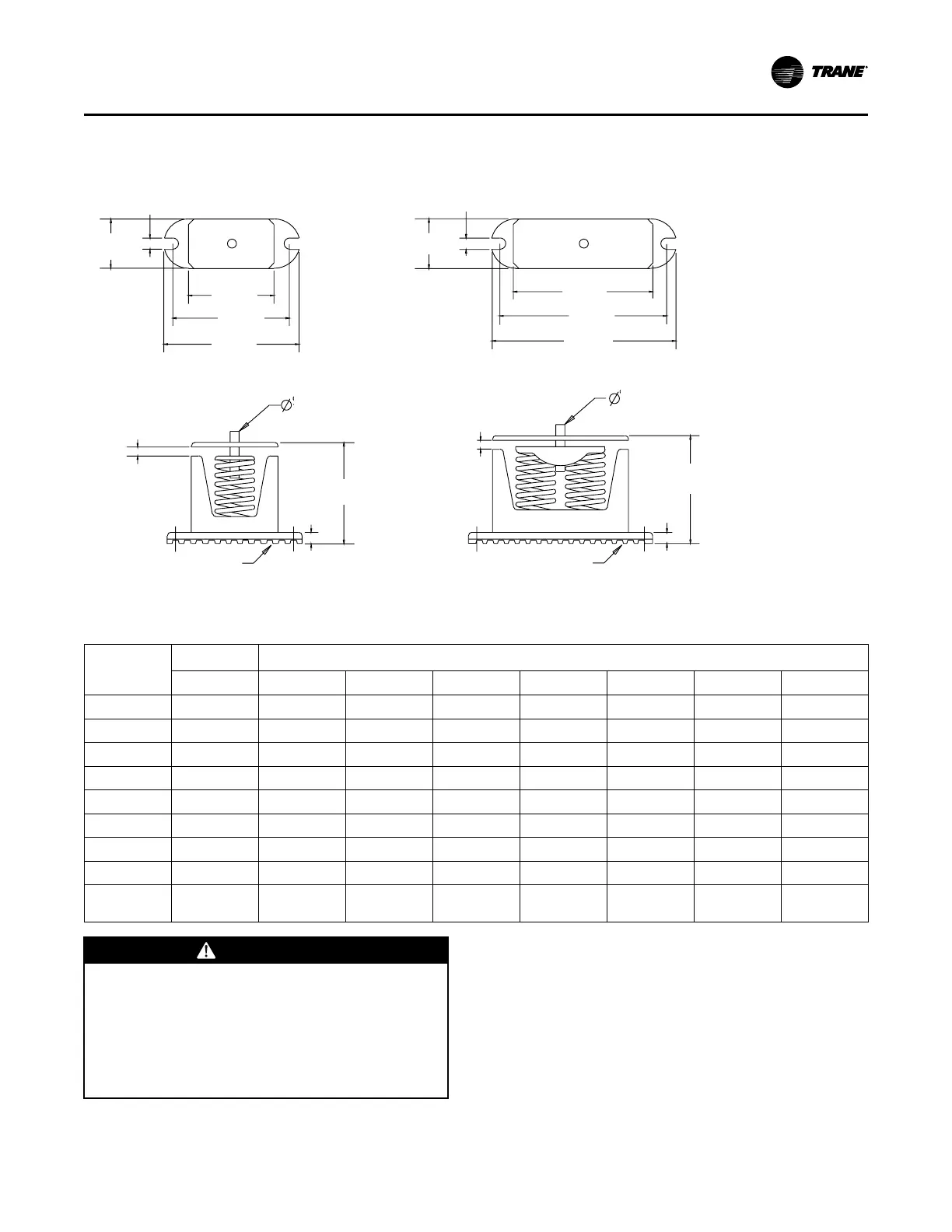
Spring Isolators (20 to 120 Ton units)
Figure 32. Spring isolators
5/8”
(15 mm)
2 3/4”
(69 mm)
4 3/4”
(122 mm)
6 1/2”
(165 mm)
7 1/2”
(190 mm)
5/8”
(15 mm)
2 3/4”
(69 mm)
7 3/4”
(198 mm)
9 1/4”
(234 mm)
10 1/4”
(259 mm)
1/2” x 5/8” lg
(13mm x 16mm)
Leveling Bolt
1/4” to 1/2” Clearance
5 5/8” (142 mm)
Operating Height
5/8” (15 mm)
CP-1
Acoustical Non-Skid
Neoprene Pad
1/2” x 5/8” lg
(13mm x 16mm)
Leveling Bolt
1/4” to 1/2” Clearance
6” (152 mm)
Operating Height
5/8” (15 mm)
CP-2
Acoustical Non-Skid
Neoprene Pad
Table 10. RAUJ spring isolator selection
Unit Size
(tons)
Mounting Location
1 2 3 4 5 6 7 8
20 CP-1D-510 CP-1D-510 CP-1D-510 CP-1D-340 - - - -
25 CP-1D-510 CP-1D-510 CP-1D-510 CP-1D-340 - - - -
30 CP-1D-510 CP-1D-510 CP-1D-510 CP-1D-340 - - - -
40 CP-1D-510 CP-1D-510 CP-1D-510 CP-1D-510 CP-1D-510 CP-1D-510 - -
50 CP-1D-510 CP-1D-340 CP-1D-510 CP-1D-510 CP-1D-900 CP-1D-675 - -
60 CP-1D-510 CP-1D-340 CP-1D-510 CP-1D-510 CP-1D-900 CP-1D-675 - -
80 CP-1D-900 CP-1D-510 CP-1D-900 CP-1D-510 CP-1D-900 CP-1D-510 CP-1D-900 CP-1D-510
100 CP-1D-900 CP-1D-675 CP-1D-900 CP-1D-675 CP-1D-900 CP-1D-510 CP-1D-900 CP-1D-510
120
C2P-1D-
1020
CP-1D-675
C2P-1D-
1020
CP-1D-675
C2P-1D-
1020
CP-1D-675
C2P-1D-
1020
CP-1D-675
WWAARRNNIINNGG
HHeeaavvyy OObbjjeecctt!!
FFaaiilluurree ttoo ffoollllooww iinnssttrruuccttiioonnss ccoouulldd rreessuulltt iinn ddeeaatthh
oorr sseerriioouuss iinnjjuurryy..
UUssee ssoolliidd ttyyppee bblloocckkss,, ii..ee.. 44"" XX 44"" wwoooodd bblloocckkss oorr
ssiimmiillaarr mmaatteerriiaall,, ttoo pprreevveenntt ccoollllaappssiinngg.. KKeeeepp
hhaannddss aanndd ootthheerr bbooddyy lliimmbbss cclleeaarr ooff eelleevvaatteedd bbaassee
rraaiill wwhhiillee iinnssttaalllliinngg iissoollaattoorrss..
Install the spring isolators at each unit mounting (load)
point, using the following procedure:
1. Elevate the unit (one side at a time) to allow access
to the base rail mounting holes.
2. Align the mounting holes in the base rail of the unit
with the positioning pin in the top of the
appropriate isolator.
3. Position the isolator to allow access to the
mounting holes in the base of the isolator.
4. Lower the unit onto the isolator. The positioning pin
on the isolator must engage into the hole of the
base rail. The clearance between the upper and
lower isolator housings should be approximately 1/
IInnssttaallllaattiioonn MMeecchhaanniiccaall

 Loading...