98
SS-SVX11K-EN
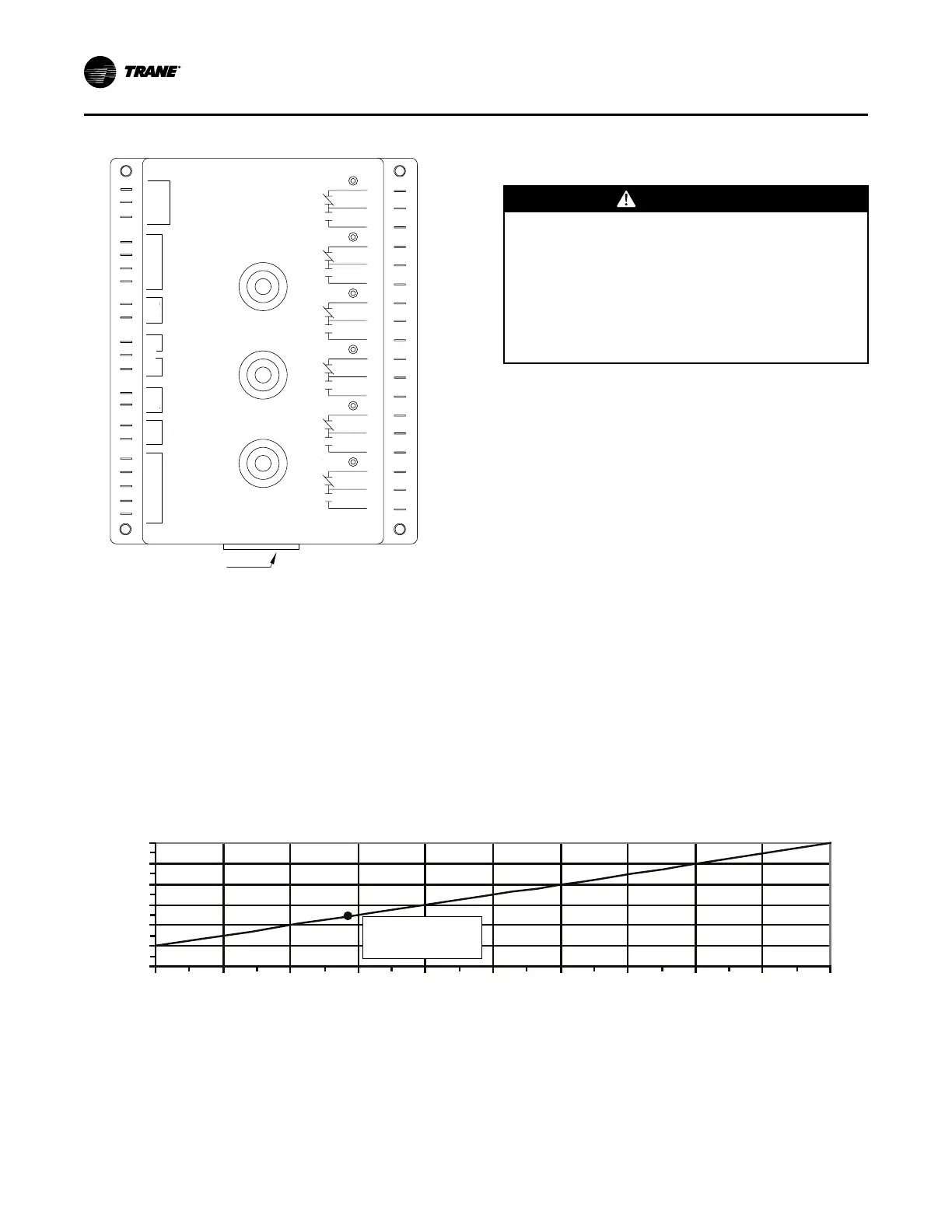
Figure 69. W7100A discharge air controller
SETPOINT °F
RESET °F
CONTROL
BAND °F
Test Plug Socket
(Remove red dust cover)
ECONO
24 VAC
CHANGE
OVER
# STAGES
SENSOR
RESET
REMOTE
SETPOINT
SATELLITE
COOL
COOL
COOL
COOL
COOL
COOL
B
C
A
B
C
A
B
C
A
B
C
A
B
C
A
B
C
A
6
5
4
3
2
1
GND
TR
TR
W
R
B
Y
10
9
T
T1
8
7
6
P
P1
5
4
3
2
1
Discharge Air Sensor Checkout
(Honeywell Sensor)
WWAARRNNIINNGG
HHaazzaarrddoouuss VVoollttaaggee!!
FFaaiilluurree ttoo ddiissccoonnnneecctt ppoowweerr bbeeffoorree sseerrvviicciinngg ccoouulldd
rreessuulltt iinn ddeeaatthh oorr sseerriioouuss iinnjjuurryy..
DDiissccoonnnneecctt aallll eelleeccttrriicc ppoowweerr,, iinncclluuddiinngg rreemmoottee
ddiissccoonnnneeccttss bbeeffoorree sseerrvviicciinngg.. FFoollllooww pprrooppeerr
lloocckkoouutt//ttaaggoouutt pprroocceedduurreess ttoo eennssuurree tthhee ppoowweerr
ccaann nnoott bbee iinnaaddvveerrtteennttllyy eenneerrggiizzeedd.. VVeerriiffyy tthhaatt nnoo
ppoowweerr iiss pprreesseenntt wwiitthh aa vvoollttmmeetteerr..
1. Verify that the main power disconnect switch and
the control circuit switch 1S2, in the unit control
panel, is “OFF”.
2. At the Discharge Air Controller, in the unit control
panel, disconnect the wire connected to Terminal
T1. Use a digital ohmmeter to measure the
resistance across Terminal T and the wire removed
from Terminal T1.
3. Use the conversion chart in Figure 70, p. 98 to
convert the measured resistance to an equivalent
temperature.
4. Measure the actual temperature at the sensor
location. If the measured resistance in step 2 is not
within ± 10.0 ohms of the actual temperature, the
sensor is out of range; replace it.
NNoottee:: Before condemning the sensor, verify that
the connecting cable resistance is not
excessive. Refer to the “Field Installed
Control Wiring” section.
5. Make all necessary repairs and reconnect the duct
sensor lead to terminal T1 on the controller.
6. Restore power to the system and turn all control
switches to the “ON” position.
Figure 70. Discharge duct sensor 6RT2 & 6RT3 “temperature vs resistance” curve
3000
3200
3400
3600
3800
4000
4200
20
(-6.7)
40
(4.4)
60
(15.6)
80
(26.7)
100
(37.8)
120
(48.9)
140
(60.0)
160
(71.1)
180
(82.2)
200
(93.3)
220
(104.4)
Resistance (Ohms)
Temperature °F (°C)
3483±10 ohms
77°F (25°C)
Economizer Actuator Checkout
((UUsseedd wwiitthh ““ZZoonnee”” oorr ““DDiisscchhaarrggee AAiirr”” TTeemmpp
CCoonnttrroolllleerr))
The following procedures should be used to verify that
the field provided economizer actuator(s) function
properly. These procedures are based on using a
typical Honeywell actuator. If another type actuator is
PPrree--SSttaarrtt

 Loading...