Installation
38 SO-SVN048A-EN
1. Install choke core support bracket (1) using 6 mm thread
rolling screws (13) so that is centered between the motor
terminals.
2. Install 4-inch din rail (2) using 6 mm thread rolling screws
(13).
3. Locate the 1F-1F3 fuse (3) (refer to Figure 34 and
Figure 38), and install on 4-inch din rail (2).
4. Install din rail end-stops (4) on din rail (2).
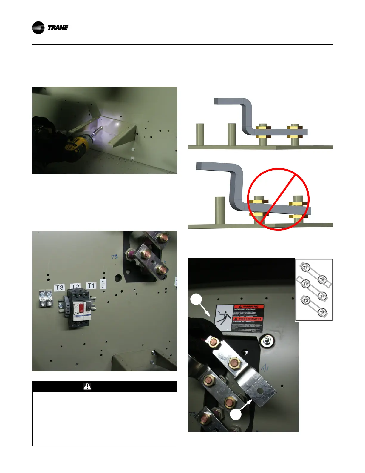
5. Install motor terminal buss bars (5/6). Torque to 40 ft·lb.
Note: Motor terminal buss bars must be flush on motor
terminal connection points; refer to Figure 41.
Figure 39. Choke core support bracket
Figure 40. Din rail/1F1-1F3 fuse install
WARNING
Backup Wrench Required!
Failure to follow instructions below could result in
death or serious injury. Use backup wrench when
installing and removing wire or buss bars from motor
terminals and inspect terminals to ensure that they are
not damaged. Motor terminals are ceramic and, if
cracked, could create an electrical hazard when power
is restored.
Figure 41. Correct and incorrect motor terminal buss
bar installation
Figure 42. Installed motor terminal buss bars; inset
shows buss bars over original terminals

 Loading...


