Installation
52 SO-SVN048A-EN
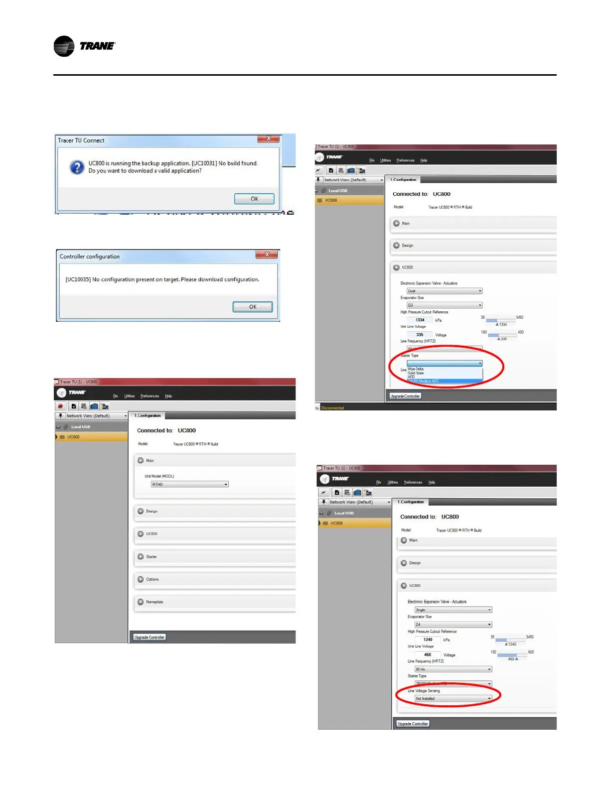
6. After the download is complete, two confirmation dialog
boxes appear. Click OK in each dialog box.
7. Tracer TU’s Configuration tab appears; refer to
Figure 86.
Important: Trane recommends configuring the unit
manually rather than browsing to an existing
Chiller Service Report electronically.
8. Because the new AFD is being retrofit with Modbus
®
client
communications, reference the Chiller Service Report in
PDF or XML to configure the unit for best results.
a. For Starter Type (located in the UC800 section or in the
Starter section, depending on actual software version
used), select TR200 Modbus
®
AFD; refer to Figure 87.
b. For Line Voltage Sensing, select Not Installed; refer
to Figure 88.
Figure 84.
Figure 85.
Figure 86.
Figure 87.
Figure 88.

 Loading...


