Alarms
RT-SVX49C-EN 13
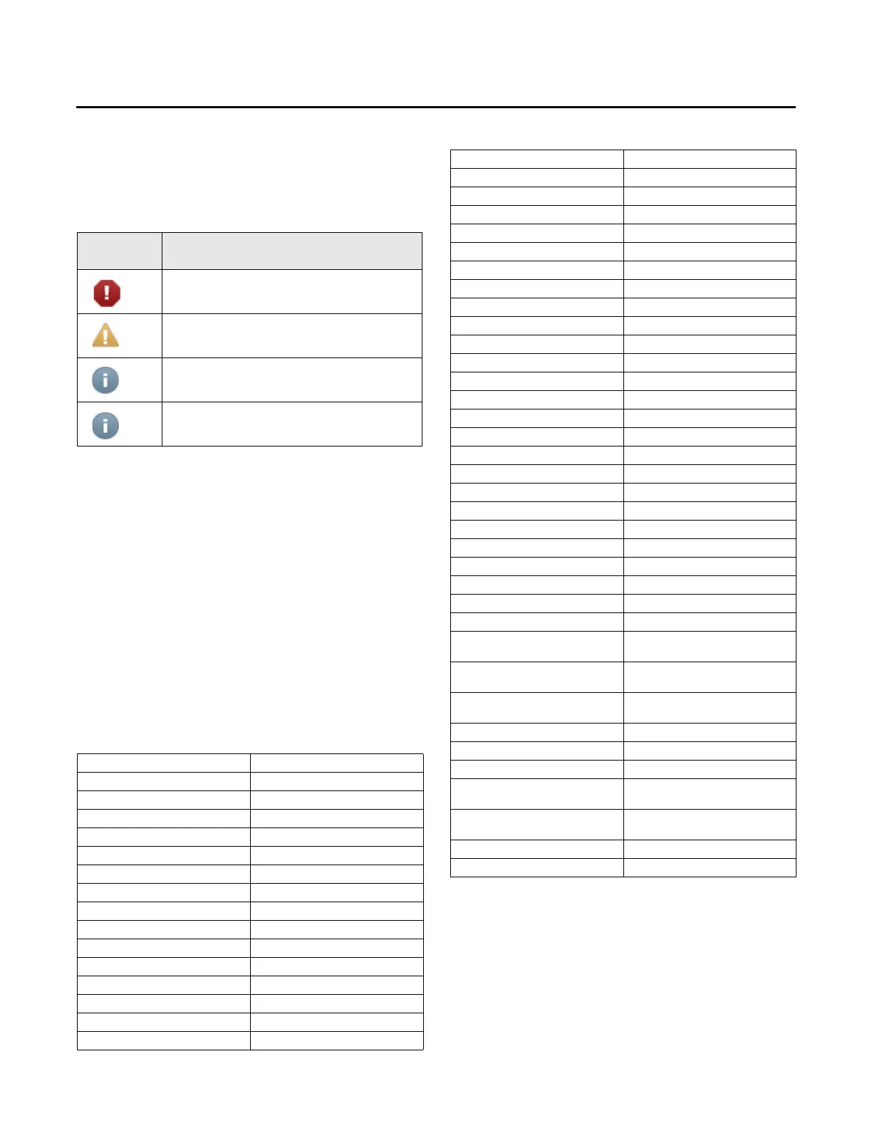
Alarm Icons
Alarms icons appear in the left-most column of the alarms
screen. They are identifiable by their shape and color.
Table 1. Alarm icons
Active
Alarm Icons Notification Class
Critical
Service Required
Advisory
Information
Sorting Alarms
To sort alarms by a category other than date and time,
touch one of the other column headings in the table. The
column heading responds by changing to blue, and the
alarms table re-sorts according to the blue column
heading. By touching the blue column heading again, the
column will change the sort direction.
• Severity: Alarms are sorted by there notification class
sho
wn in the table above in either descending or
ascending order.
• Date and Time (the default sort): Alarms are sorted by
timestam
p in either descending or ascending order.
• Description: Alarms are sorted alphabetically by
de
scrip
tion in either descending or ascending order.
Table 2. List of alarms
Space Temp Sensor Failure Outdoor Temp Sensor Fail
Compressor 1 HPC Lockout Compressor 1 LPC Lockout
Comp 1 Disable Input/LPC Compressor 2 HPC Lockout
Compressor 2 LPC Lockout Comp 2 Disable Input/LPC
Smoke Detector Heat Failure
Dirty Filter Supply Fan Failure
Emergency Stop Frostat™ Trip
Mixed Air Temp Sensor Fail OA Humidity Sensor Failure
Return Air Temp Sensor Fail Return Air RH Sensor Failure
Coil Temp Sensor #1 Fail Demand Defrost Fault A
Demand Defrost Fault B Demand Defrost Fault C
Demand Defrost Fault D Defrost Default Mode
Local Cool Setpoint Fail Local Heat Setpoint Fail
Vent Override – Purge Vent Override – Exhaust
Vent Override – Pressurize Drain Pan Overflow
Freezestat Tripped Supply Air Temp Sensor Fail
CO
2
Sensor Failure CO
2
Setpoint Failure
Space Humidity Sensor Fail Dehumid Setpoint Failure
Airflow Sensor Fail Min OA Flow Setpoint Fail
Space Pressure Setpoint Fail Space Pressure Sensor Fail
Heating High Temp Limit Open Flame Rollout Switch Open
Inducer Proving Switch Fail No Flame Sensed on heat call
Flame Sensed w/Gas Valve Off Gas Heat Module Failure
Economizer Actuator Fault Morning Warmup Setpoint Fail
SA Reset Amount Failure SA Temp Cool Setpoint Fail
SA Temp Heat Setpoint Fail SA Reset Setpoint Failure
SA Press Setpoint Fail SA Pressure Deadband Fail
Supply Air Press Sensor Fail SA High Press Limit
SA Pressure PWM Fault Comp 1 Disable Input/HPC
Comp 2 Disable Input/HPC CO2 Low Limit Setpoint Fault
Exh/Ret Fan Proving Failure RTOM Comm Fail
RTEM Comm Fail RTAM Comm Fail
RTVM Comm Fail VSM Comm Fail
SA Reheat Setpoint Failure RTDM Comm Fail
Space Press Deadband Fail Mod Dehumid Config
Ent Evap Temp Sensor Fail Coil Temp Sensor #2 Fail
SA Temp Heat Setpoint Fail Demand Defrost Fault A Ckt 2
Demand Defrost Fault B Ckt 2 Demand Defrost Fault C Ckt 2
Defrost Default Mode Ckt 2 Demand Defrost Fault A Ckt 1
Demand Defrost Fault B Ckt 1 Demand Defrost Fault C Ckt 1
Defrost Default Mode Ckt 1 Exhaust Fan Setpoint Fail
IGN1 Communications Timed out IGN2 Communications Timed out
DCV Min Position Setpoint Fail (@
Full Fan
Speed)
De
sign Min Position Setpoint Fail
(@ Full Fan Speed)
Enthalpy Setpoint Fail
Design Min Position at Minimum
Fan Speed Fail
DCV Min Position at
Minimum Fan
Speed Fail
Desig
n Min Position at Midpoint
Fan Speed Fail
DA Cool Setpoint Fail PWM Max Fan Spd Setpt Fail
Compressor 3 HPC Lockout Compressor 3 LPC Lockout
Comp 3 Disable Input/LPC Comp 3 Disable Input/HPC
BAS Interface Comm Fail
Unit Not Economizing When It
Sho
uld Be
Unit Econo
mizing When It Should
Not Be
Outdoor Air Damper Not
Modula
ting
Excessive Outdoor Air Mixed Air Low Limit Cycle Active
VSPD Compressor Drive Fault VSPD Compressor Drive Lockout
Table 2. List of alarms (continued)
 Loading...

