EasyManuals Logo
Home>UFactory>Robotics>LITE 6

UFactory LITE 6 User Manual

UFactory LITE 6
165 pages
To Next Page IconTo Next Page
To Previous Page IconTo Previous Page
Page #17 background imageLoading...
Page #17 background image
Lite 6 User Manual-Hardware Section
1. Hardware Installation Manual
1.1. The Hardware Composition of the robot
1.1.1. Hardware Composition
The composition of robotic arm hardware includes:
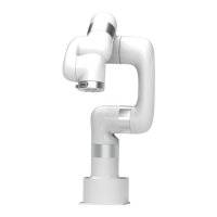
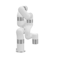
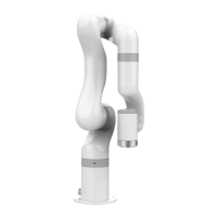
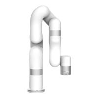
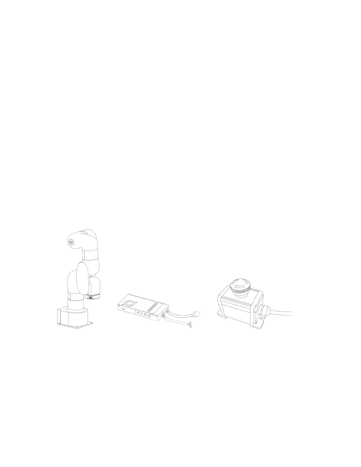
Robotic Arm(Figure 2-1)
Power Adapter (Figure 2-2)
Emergency Stop Button (Figure 2-3)
The Lite 6 robotic arm system consists of a base and rotary joints, and
each joint represents a degree of freedom. From the bottom to the top,
in order, Joint 1, Joint 2, Joint 3, etc. The last joint is known as the
tool side and can be used to connect end-effector (e. g. gripper, vacuum
gripper, etc).
Figure 2-2
Figure 2-1
Figure 2-3

Other manuals for UFactory LITE 6

Questions and Answers:

Question and Answer IconNeed help?

Do you have a question about the UFactory LITE 6 and is the answer not in the manual?

UFactory LITE 6 Specifications

General IconGeneral
BrandUFactory
ModelLITE 6
CategoryRobotics
LanguageEnglish

Related product manuals