UPO2000CS series User Manual
18
horizontal position knob. Press in the knob returns the displacement back to 0.
⑥. Trigger Status: Displays trigger source, type, slope, coupling, level, etc.
a) Trigger Source: There are seven states: CH1~CH4, AC Line, EXT, and EXT/5. CH1~CH4 will each be
of a different trigger color. For example,
is CH1.
b) Trigger Type: The types are edge, pulse width, video, slope, and advanced trigger. For example,
is
an edge trigger.
c) Trigger Slope: The types are rising, falling, and rising/falling. For example,
is rising.
d) Trigger Coupling: The types are DC, AC, high frequency, low frequency and noise. For example,
indicates DC coupling.
e) Trigger Level: Indicates the current trigger level value, can be adjusted with the trigger level knob.
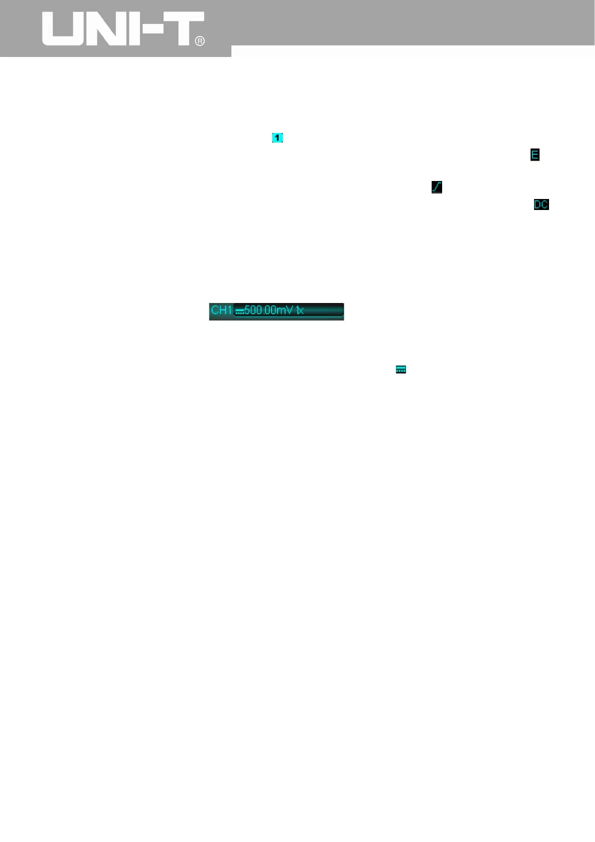
⑦. CH1 Vertical Identification: Displays CH1 activation state, channel coupling, bandwidth limit, vertical
profile, and probe attenuation coefficient.
a) Channel Activation State:
When the background color is consistent
with the channel color, the channel is activated. Press CH1~CH4 to open/close the corresponding
channel.
b) Channel Coupling: Includes DC, AC, and grounding. For example,
is DC coupling.
c) Bandwidth Limitation: When the bandwidth limit function is turned on, a BW icon will appear in the
display.
d) Vertical Profile Position: When CH1 is activated, the vertical profile can be adjusted with the vertical
scale knob.
e) Probe Attenuation Factor: Displays CH1 probe attenuation coefficient: 0.001X, 0.01X, 0.1X, 1X, 10X,
100X, and 1000X
⑧. CH2 Vertical Indentification: Same as
○
7 , but for CH2
⑨. CH3 Vertical Indentification: Same as
○
7 , but for CH3
⑩. CH4 Vertical Indentification: Same as
○
7 , but for CH4
⑪. Operation Menu: Displays the current operation menu. Use F1 ~ F5 to navigate through menu contents
⑫. Analog Channels: Displays CH1~CH4 waveforms with matching tag and waveform color.
 Loading...