UPO2000CS series User Manual
24
CH4
EXT、EXT/5 Set external trigger or external trigger/5 as the source
AC Line Set AC line as trigger
Slope
Rise Set the rising edge of the signal trigger
Fall Set the falling edge of the signal trigger
Rise/fall Set the rising edge and the falling edge as trigger
Trigger
Setting
Enters the trigger settings menu, see below
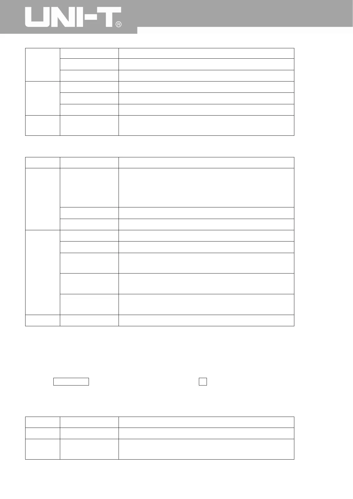
Trigger Setting Menu
Functions Options Descriptions
Trigger
Mode
Auto When the signal input is not triggered, the system automatically
collects the waveform data and displays the scan baseline on
the screen. When a trigger signal is generated, it automatically
turns to the trigger scan.
Normal The data acquisition stops when the signal is not triggered.
Single Generates a trigger and stops
Trigger
Coupling
DC Blocks the AC component of the signal
AC AC and DC components of the trigger signal
High frequency
suppression
Suppression of signal frequency above 50kHz
Low frequency
suppression
Suppression of signal frequency below 5kHz
Noise suppression
Suppress the noise of the trigger signal, trigger sensitivity is
halved.
Return Return to first level menu
3.3 Pulse Width Trigger
Pulse width trigger can set the capture condition by the pulse width.
Press the TRIG MENU button to enter the trigger menu. Press F1 to select trigger type, and set the pulse
width using the multipurpose knob.
The pulse width trigger menu is shown below:
Functions Options Descriptions
Type Pulse Width
Sources
CH1, CH2, CH3,
CH4
Set any one of the CH1~CH4 as a trigger signal
 Loading...