2. Dual Robot Calibration
2.1 Required Equipment
The method requires a Dual Robot Calibration Kit from Universal Robots (purchase number: 185500) and
one pair of UR3, UR5 or UR10 robots with control box CB3. The robot bases are connected with a device
and the robot tools are connected by a device (Appendix A). This creates a closed chain where the distance
between the bases and the tools are fixed to known distances. In addition, the calibration horse, (Figure 2.2),
have holes with threads at the bottom for temponary and long term storage of screws.
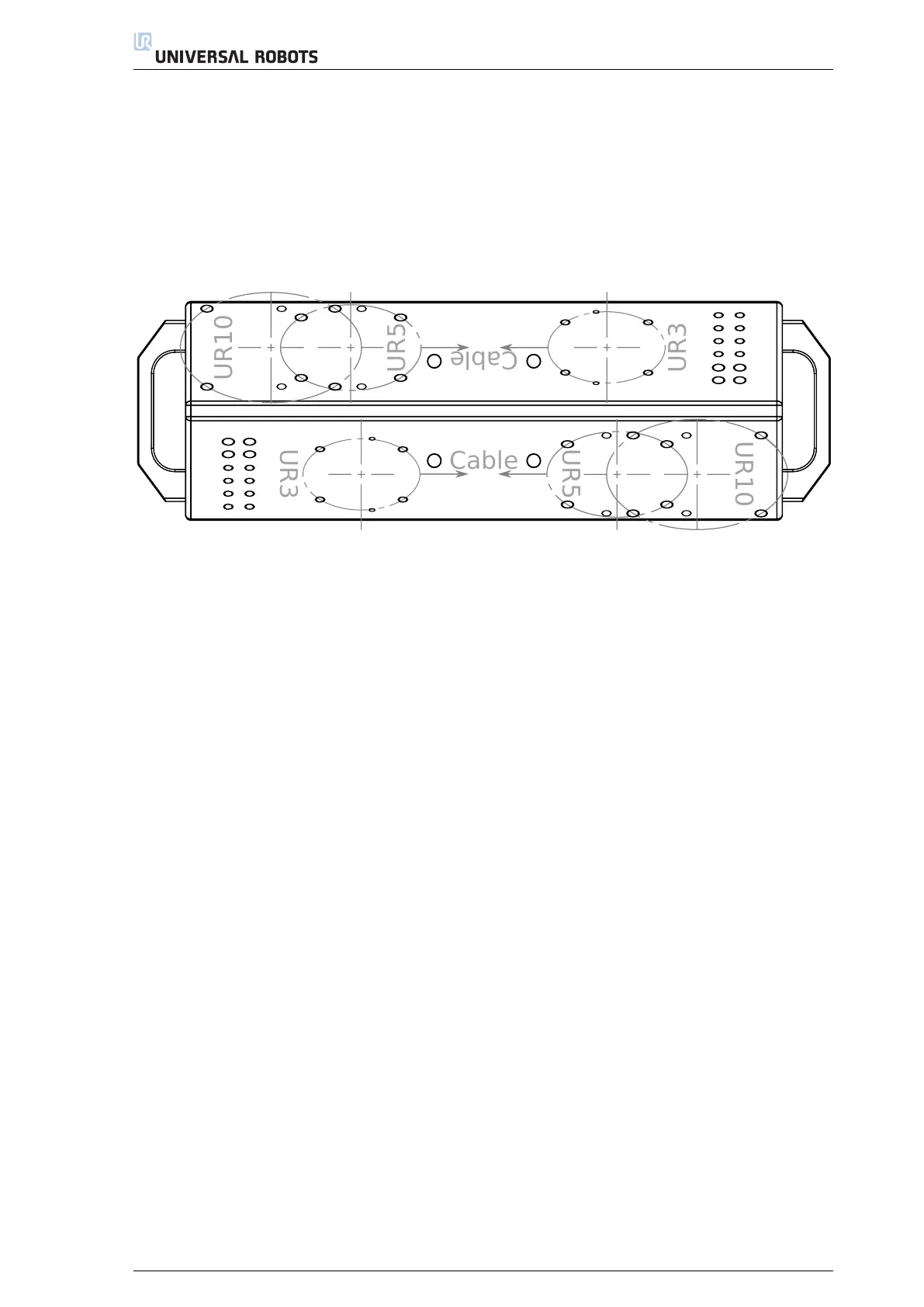
Please note that the UR3, UR5 and UR10 are mounted differently on the Calibration Horse and that their
cables are pointing toward each other, as illustrated in Figure 2.2.
UR5
UR10
UR5
UR10
Cable
Cable
UR3
UR3
Figure 2.2: A sketch of the Dual Robot Calibration Horse and where the UR3, UR5 or UR10 robot can be
mounted
To complete the assembly, mount the two handles at each end of the Calibration Horse with two M8-
1.25x25, each. The handles and screws are included in the Dual Robot Calibration Kit.
Required equipment:
• A pair of UR3, UR5 or UR10 robots, respectively, to be calibrated
• A stand with a height of at least 0.5 m for the Calibration Horse
• Dual Robot Calibration Kit from Universal Robots with purchase number: 185500, including:
– The UR Dual Robot Calibration Horse with alignment pins (Figure A.1, Appendix A)
– The UR Dual Robot Calibration Tool Connector with alignment pins (Figure A.2, Appendix A)
–
Four M8-1.25x70 to mount the Calibration Horse to the stand (may differ depending on the robot
stand)
– Eight M8-1.25x25 screws with washers to mount UR5 and UR10 robots to the Calibration Horse
–
Eight M6-1.0x25 screws with washers to mount the robot tools to the Calibration Tool Connector
– Eight M6-1.0x25 screws to mount UR3 robots to the Calibration Horse
– One Go tool used in the validating procedure, (Figure A.3, Appendix A)
– One No Go tool used in the validating procedure (Figure A.4, Appendix A)
Exception:
•
The alignment pin for the tool connector, should not be used when calibrating UR5s produced prior to
end of 2014. This is due to the calibration requiring an improved version of the tool flange in UR5.
3

 Loading...


