Installation
Installation and maintenance instructions ecoTEC 0020173113_01 17
4
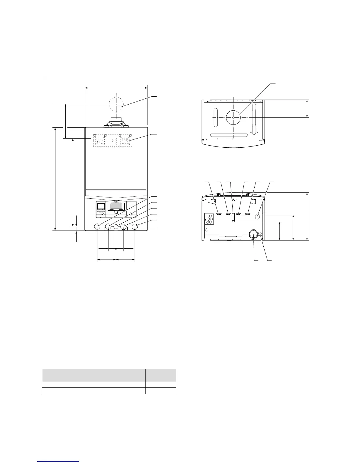
4.5 Dimension drawing and connection
measurements
720
20
35 35
624
335
180
125
125
100100
440
A
2
1
8
3
4
5
6
7
7
9 10
6
3 4 5
11
4.4 Connection measurements in mm
Key
1 Wall breakthrough for air/flue gas duct
2 Hanging bracket
3 Heating flow (Æ 22 x 1.5)
4 Hot water connection (Æ 15 x 1.5)
5 Gas connection (Æ 15 x 1.5)
6 Cold water connection (Æ 15 x 1.5)
7 Heating return (Æ 22 x 1.5)
8 Air/flue gas duct connection
9 Condensate trap
10 Condensate discharge connection, Æ 19 mm
11 Heating expansion relief valve drain line connection, Æ 15 mm
Minimum dimension from wall bracket to center
line of air/flue gas duct wall breakthrough
Dimension A
[mm]
60/100 with elbow 87°, PP 175
80/125 with elbow 87°, PP 223
4.4 Dimension A for air/flue gas duct wall breakthrough with
VU and VUW boilers
 Loading...


