Electrical installation
32 Installation and maintenance instructions ecoTEC 0020173113_01
8
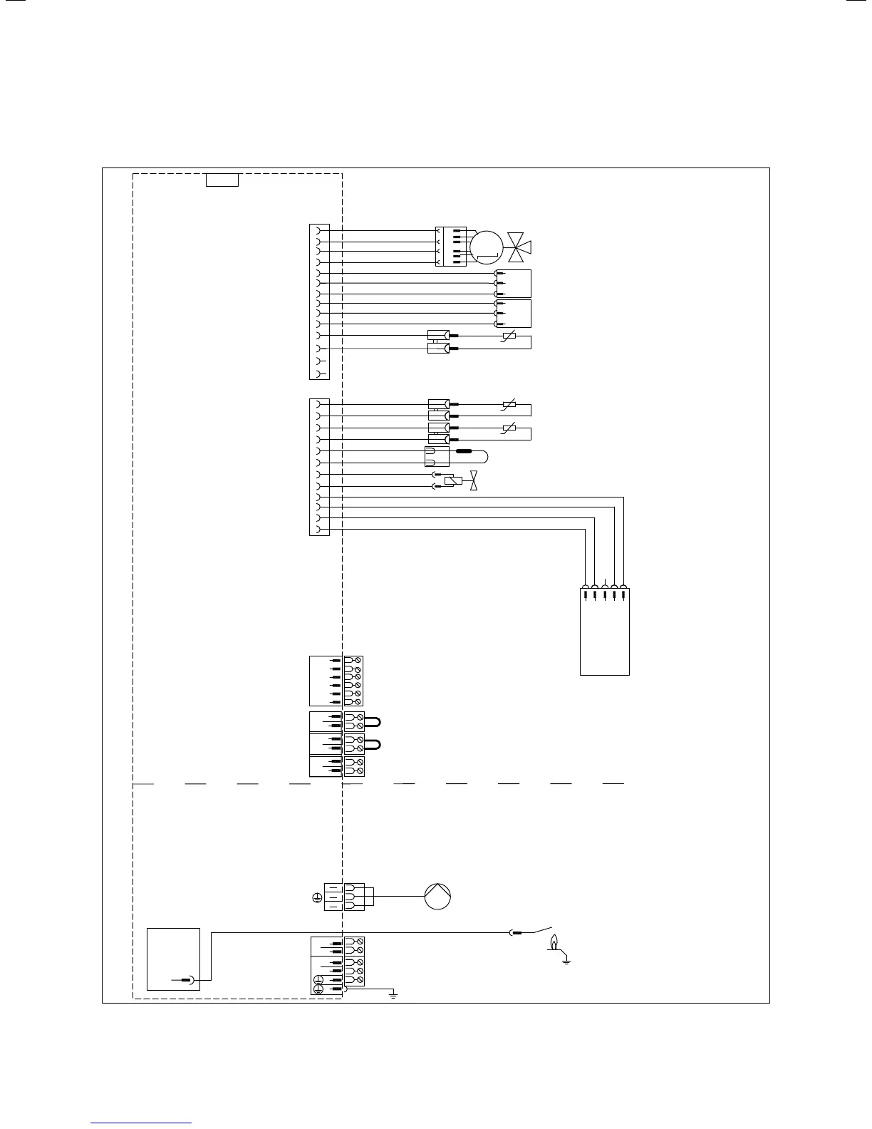
8.6 Connection wiring diagrams
Circulation pump remote control
1
DCF connection
Earth
Earth
External sensor
Flow sensor (optional)
6
Ignition
trans-
former
Bus connection
(Controller/room th. digital)
M
X2
8
17
7
18
14
13
4
12
5
7
7
16
4
3
17
24 V
230 V~
X51
5
8
15
13
12
2
X20
X41
X106
2
3
11
6
1
Internal pump *
Ignition
electrode
Mains connection
Appliance earth
X18
X1
* ... variant-dependent
230 V AC room thermostat *
No function *
+ 24 V
PWM
Earth
Hall signal
Diverter valve
1
3
4
red
Flow sensor
blue
Return sensor
Display
Connection
Safety fuse
Burner
off
RT
24
Bus
Water pressure
sensor
Contact thermostat/burner off
1
2
3
4
5
6
1
2
3
Impeller sensor
orange
J
Warm start sensor
J
J
Fan
12
45
+
-
FB
AF
RF
DCF
0
0
L
N
L
N
RT
24 V DC room thermostat
blue
pink
Edge
connector
green
turquoise
Gas valve
+
8.3 Wiring diagram for the ecoTEC 26 (VUW) electronics box

 Loading...


