Commissioning
40 Installation and maintenance instructions ecoTEC 0020173113_01
10
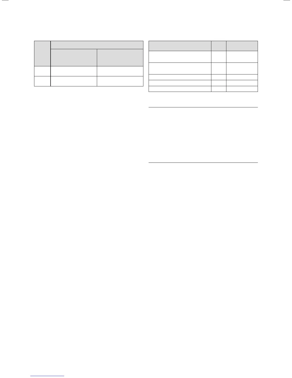
Boiler
Gas used on the Channel Islands
Minimum pressure at
reference test point in
kPa (mbar)
Maximum pressure at
reference test point in
kPa (mbar)
22 1.0 (10) 1.7 (17)
26 1.0 (10) 1.7 (17)
10.2 Gas inlet working pressure at the reference test point
If the supply pressure is out of tolerance contact your
Emergency Service Provider.
If the gas inlet working pressure at the reference test point
(1) is not within the permissible range and you cannot cor-
rect the failure, notify the gas supply company or the Vail-
lant Service Solutions (0870 6060 777) and proceed as fol-
lows:
> Take the boiler out of operation by
– terminating test program P.01 as described in ¬sec-
tion10.2.
– Only for VUW-boilers: Allow the boiler to cool down by
turning off water taps and allow pump overrun to
operate for a minimum of two minutes.
> Close the gas isolation valve of the boiler.
> Remove the pressure gauge and retighten the sealing
screw (1) for the measuring nipple.
> Turn on gas at the gas isolation valve.
> Make sure that there is no leakage at the sealing screw.
> Turn off gas at the gas isolation valve.
> Put the front casing back on.
> Turn off electrical supply to the boiler.
> You must not start up the boiler.
If the gas inlet working pressure is within the permissible
range, proceed as follows:
> After five minutes in full load mode, compare the meas-
ured CO
2
value with the target CO
2
value (value with
front casing removed ¬ Table 10.3).
> If this value deviates from the target value, adjust the
corresponding CO
2
value by turning the bolt (2)
(¬ Fig. 10.5). Use a 2.5mm Allen key for this.
– Turn to the left: higher CO
2
concentration,
– Turn to the right: lower CO
2
concentration.
i
Gas used on the Channel Islands: Only perform
the adjustment in small increments (approxi-
mately 1/4 turns), and wait approximately 1 min-
ute after each adjustment until the value stabi-
lises.
Settings
Unit
Gas used on the
Channel Islands
CO
2
after 5 minutes full load mode
with boiler front casing fitted
Vol.–%
10.0 ± 0.
5
CO
2
after 5 minutes full load mode
with boiler front casing removed
Vol.–%
9.8 ± 0.
5
Set for Wobbe index Ws kWh/m
3
6.6
CO value with full load ppm < 250
CO/CO
2
< 0.0026
10.3 Target values for the gas ratio setting
a
Danger!
Risk to life due to poisoning!
CO is an extremely toxic gas. Risk to life
due to excessive CO concentrations.
> If you are not able to adjust the boiler
correctly and the flue gas values remain
higher than allowed in ¬table10.3, call
the Vaillant Service Solutions (0870
6060 777).
> Do not start up the boiler!
> Take the boiler out of operation by
– terminating test program P.01 as described in ¬sec-
tion10.2.
– Only for VUW-boilers: Allow the boiler to cool down by
turning off water taps and allow pump overrun to
operate for a minimum of two minutes.
> Close the gas isolation valve of the boiler.
> Remove the pressure gauge and retighten the sealing
screw (1) for the measuring nipple.
> Open the gas isolation valve of the boiler.
> Make sure that there is no leakage at the sealing screw.
> After the adjusting work is complete, put the covering
cap back on again (1) (¬ Fig.10.5).
> Remove the CO
2
measuring instrument from the measur-
ing connection and close the measuring connection
again.
> Put the front casing back on.
> Reset boiler controls for normal operation.
> Record the appliance gas inlet working pressure (kPa
resp. mbar) in the Benchmark gas boiler commissioning
checklist.
10.11 Checking for tightness of the flue gas
installation and flue gas recirculation
> Check the integrity off the flue gas installation according
to TB 008.
> Should the flue gas installation be longer than 2 m we
strongly recommend to check the system for flue gas
recirculation as described below.

 Loading...


