Inspection and maintenance
Installation and maintenance instructions ecoTEC 0020173113_01 55
12
12.2.1 Filling the boiler and the heating
installation
A description of how to fill the boiler and the heating instal-
lation is provided in ¬ section 10.5.
12.2.2 Draining the boiler
> Close the service valves of the boiler.
> Start test program P.06 (diverter valve mid-position)
(¬ section 10.5).
> Open the drain valves on the service valves.
> Make sure that the cap of the automatic air vent on the
internal pump is open so that the boiler can be drained
fully.
12.2.3 Draining the entire heating installation
> Attach a hose to the draining device on the system.
> Bring the open end of the hose to an appropriate drain
point.
> Start test program P.06 (diverter valve mid-position)
(¬ section 10.5).
> Make sure that the service valves on the boiler and the
cap of the automatic air vent on the internal pump is
open.
> Open the drain cock.
> Open the purging valves on the radiators.
Start from the highest radiator and then work from the
top to the bottom.
> Once the water has drained off, close the purging valves
of the radiators and the drain cock.
12.3 Carrying out maintenance work
12.3.1 Removing the compact thermal module
a
Danger!
Risk of being burned or scalded by hot
components!
There is danger of being burned or scalded
at the compact thermal module and at all
water-carrying components.
> Only carry out work on these compo-
nents if they have cooled down.
The compact thermal module consists of five main compo-
nents:
1. Speed-regulated fan
2. Gas/air mixture fitting
3. Gas supply (mixture pipe) to the premix burner
4. Burner door
5. Premix burner
> Switch off the boiler using the on/off switch.
> Close the gas isolator cock on the boiler.
> Close the service valves on the boiler.
> Remove the front casing from the boiler (¬ section 4.7).
> Fold the electronics box forwards (¬ section 8.2).
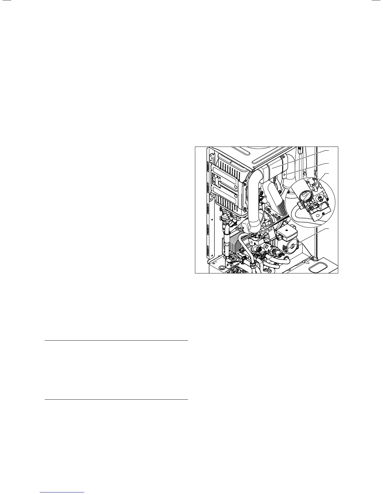
1
2
3
4
12.3 Remove the air intake pipe
> Unscrew the retaining screw (2, ¬ fig. 12.3) and detach
the air intake pipe (1, ¬ fig. 12.3) from the intake stub.
> Unscrew either the cap nut (3, ¬ fig. 12.3) from the gas
valve or the cap nut (4, ¬ fig. 12.3) between the gas
pipes.
> Secure the gas pipe against twisting by holding the pipe
against the spanner flat when undoing the cap nut.
 Loading...


