Commissioning
42 Installation and maintenance instructions ecoTEC 0020173113_01
10
You can display the current operating condition of the
boiler in the "Live monitor" on the boiler display (¬ sec-
tion 13.2.1).
10.13.1 Checking the heating mode
> Switch on the boiler.
> Make sure that there is a heat requirement.
> Activate the Live monitor (¬ section 13.2.1).
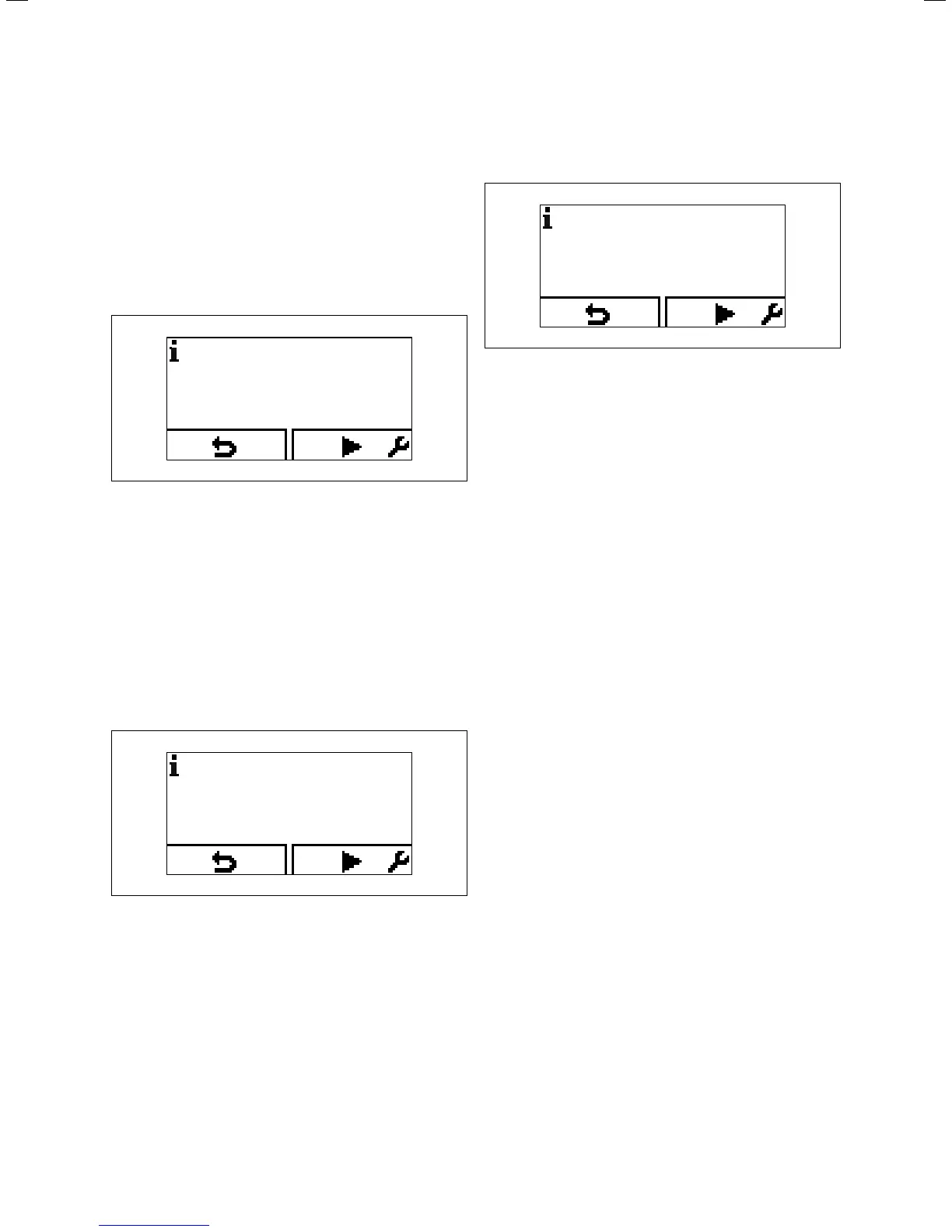
S.04
10.10 Live monitor – display during heating mode
If the boiler is operating correctly, the display will show sta-
tus code "S.04".
10.13.2 Checking the hot water generation (VUW
boilers only)
> Switch on the boiler.
> Open a hot water valve all the way.
> Activate the Live monitor (¬ section 13.2.1).
If hot water generation is working correctly, the display
shows "S.14".
S.14
10.11 Display for hot water generation (VUW boilers only)
10.13.3 Checking hot water generation
(VU boilers only)
> Switch on the boiler.
> Switch on the connected domestic hot water cylinder.
> Make sure that the cylinder thermostat is requesting
heat.
> Activate the Live monitor(¬Kap.13.2.1).
If the cylinder is being charged correctly, status code “S.24”
appears in the display.
S.24
10.12 Display during cylinder charging (VU boilers only)
> If you have connected the controller for the heating
installation using a two-wire eBUS line, then set the hot
water temperature at the boiler to the maximum possible
temperature (¬table11.1).
> A
djust the target temperature for the connected domes-
tic hot water cylinder to the controller.
10.14 Final flush of the heating system ("hot")
> Operate the appliance until the boiler and the heating
system are up to temperature.
> Check the heating system for leaks.
> Connect a hose to the drain valve located at the lowest
position of the heating system.
> Shut off the boiler, open the drain valve and all purge
valves on the radiators and allow the water to flow out of
the heating system and the boiler quickly and fully.
> Close the drain valve.
> Fill the heating system again with water as described in
¬ section 10.5.3.
> Re-fill the system until the system design pressure of
0,1 MPa (1,0 bar) is attained. (The actual reading on the
digital pressure gauge should ideally be 0,05 MPa
(0,5 bar) plus an additional pressure corresponding to
the highest point of the system above the base of the
boiler – 10 m head equals an additional 1 bar reading on
the pressure gauge. The minimum pressure should not
be less than 0,1 MPa (1 bar) in any installation.) If the sys-
tem is to be treated with an inhibitor it should be applied
at this stage in accordance with the manufacturer’s
instructions. Further information can be obtained from
Sentinel, Betz Dearborn Ltd., Tel: 0151 420 9595, or Fer-
nox, Alpha–Fry technologies. Tel: 0870 8700362.
> Refit the boiler casing (¬ section 4.7).
> Attach the bottom cover to the boiler by sliding the front
edge of the cover into the lip at the bottom front edge of
the appliance chassis.
> Carefully push the rear of the bottom cover upwards
until the spring retaining clips engage at the side of the
appliance. It may be necessary to adapt the bottom
cover by removing the easy break sections.

 Loading...


