Hydraulic installation
Installation and maintenance instructions ecoTEC 0020173113_01 23
6
6.5 Low loss header
A low loss header disconnects the boiler from the heating
system. The system is no longer dependent on the remain-
ing feed head of the boiler. In conjunction with the heating
pump, the low loss header ensures that a sufficiently high
minimum quantity of water is always circulating through
the boiler. No electrical accessories are required in order to
use a low loss header.
6.6 Connecting the condensate discharge
pipework
a
Danger!
Risk of death from flue gases!
An empty or insufficiently filled condensate
trap may allow flue gas to escape into the
room air.
> Make sure that the condensate trap is
filled with water when switching on the
boiler.
a
Danger!
Risk of death from flue gases!
If the condensate discharge pipework is
connected tightly to a fixed connection to
the waste water piping, the internal conden-
sate trap can be drained fully.
> Do not connect the condensate discharge
pipework tightly to the waste water
piping.
ecoTEC boilers are equipped with a condensate trap that
continually deposits the contents to the discharge pipe.
7
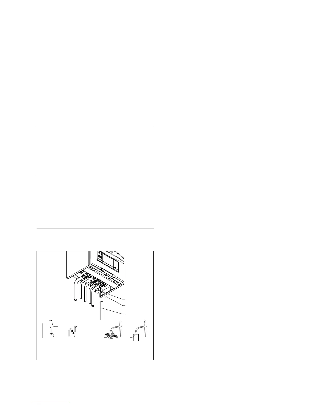
d
Soakaway
c
6
5
Gulley
a
Internal
stackpipe
3
4
3
b
Internal
discharge system
1
2
3
6.4 Condensate discharge pipework (example: VUW boiler)
> Connect the condensate discharge (1) of the boiler to a
condensate discharge pipework (3) which has a minimum
internal diameter of 19 mm (22 mm outside diameter for
all external pipes) and is made from an acid-resistant
material (e.g. plastic overflow pipe).
i
The condensate drain pipework must have a
continuous fall (45 mm per metre) and should
whenever possible terminate at a suitable drain
point within the heated envelope of the build-
ing that will remain frost free under long peri-
ods of low external temperatures.
> During installation remove all burs from inside of cut
pipe work and avoid excessive adhesive which may trap
small pockets of water close to the pipe wall which can
freeze and build into a larger ice plug.
> As with other pipe work insulate the condensate dis-
charge pipe to minimise any risk of freezing and beware
when crossing cavities that the fall is maintained and the
pipe sleeved.
> The condensate discharge pipework must terminate in a
suitable location.
Further information can be obtained from "BS 6798 Specifi-
cation for installation of gas–fired boilers of rated input not
exceeding 70 kW net". Before starting up the boiler, the
condensate trap (2) must be filled with water, as described
in the relevant section.
6.7 Connecting the discharge pipe to the
expansion relief valve on the boiler
The expansion relief valve for the heating installation is
integrated in the boiler.
> Install the discharge pipe for the expansion relief valve
so that it does not interfere with the removal and fitting
of the condensate trap.
i
We recommend not to shorten the discharge
pipe supplied.
> Leave an installation space of at least 180 mm beneath
the condensate trap.
 Loading...


