Doc: 70-00-0958A V1.0, 20221102 © Vector Controls GmbH, Switzerland Page 20-34
Subject to change without notice www.vectorcontrols.com
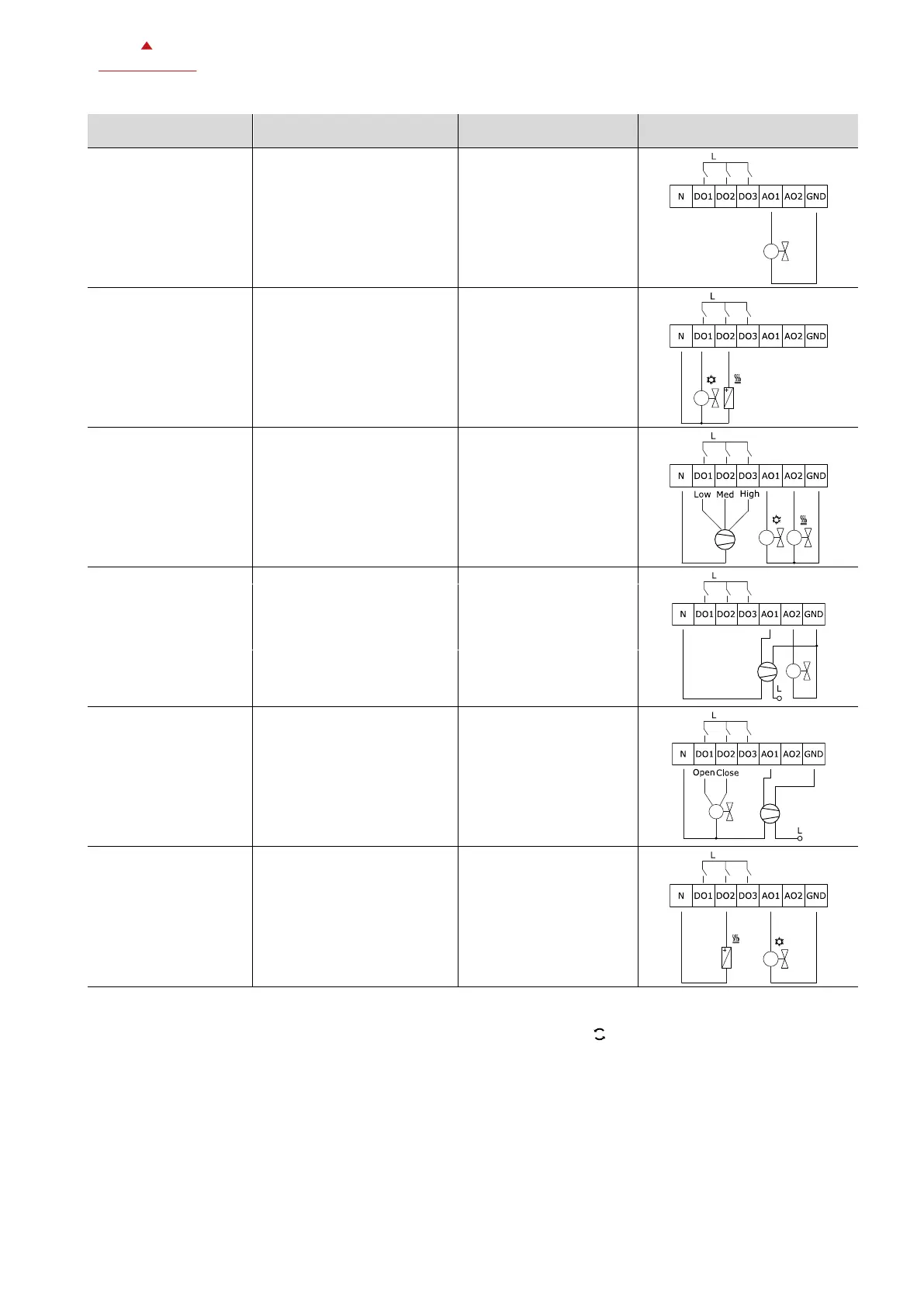
P200, P201, P203,
P207, P215 settings
Wiring diagram of outputs
• Floor heating / chilled
ceiling system
• AO1: 0-10V modulating
valve
Floor heating
modulating valve
Chilled ceiling
modulating valve
2 = Modulating valve
0-10V
Heated/Chilled ceiling
modulating valve
• Chilled ceiling system
• DO1: Cooling
• DO2: Electric heater
(optional)
Chilled ceiling
On/off valve
8 = Chilled ceiling
system
Chilled ceiling
On/off valve
Electric heater
0 or 1 (optional electric
heater)
• 4 pipe system
• DO1-3: 3-stage Fan
• AO1: 0-10V Cooling valve
• AO2: 0-10V Heating valve
4-pipe manual heating or
cooling, 2 analog valves, 3
stage fan
2 = Modulating valve
0-10V
4-pipe auto heating or
cooling, 2 analog valves, 3
stage fan, RT1 as digital
changeover input (NO)
• 2 pipe system
• AO1: 0-10V analog fan
• AO2: 0-10V modulating
valve
2-pipe manual heating or
cooling, analog valve and fan
No DO used
2 = Modulating valve
0-10V
6 = 6 fan speeds (in
manual fan mode)
• 2 pipe system
• AO1: Analog fan
• DO1/DO2: 3-position
valve
2-pipe heating or cooling, 3-
position valve
6 = 6 fan speeds (in
manual fan mode)
• Chilled ceiling system
• AO1: Modulating valve
• DO2: Electric heater
Chilled ceiling system
(modulating valve) with
electric heater enabled
2 = modulating valve
0-10V
5.6.4 Manual vs. auto heat/cool change
Manual heating or cooling allows the user interface (via Controlling Mode button ) and Modbus master to change
between heating and cooling. No input (RT1/2) can use the function “Heat/cool changeover” (P400/P402 = 2).
To allow only Modbus master control the heat/cool state parameter, P107(Enable manual control of heat/cool/fan only)
must be set to 0 = OFF. Modbus master can control the Controlling mode (heat/cool/fan only) with controller runtime data
D1101.
Auto heat/cool changeover allows one of the inputs (RT1/2, where RT1 has higher priority) to act as a control input for
heat/cool changeover. See chapter 5.9 Temperature and digital inputs, page 28. User interface and Modbus master
control of heat/cool change are disabled in auto heat/cool application (P200 = 3 or 5). Via user interface the user can only
change to fan only.

 Loading...