Doc: 70-00-0958A V1.0, 20221102 © Vector Controls GmbH, Switzerland Page 25-34
Subject to change without notice www.vectorcontrols.com
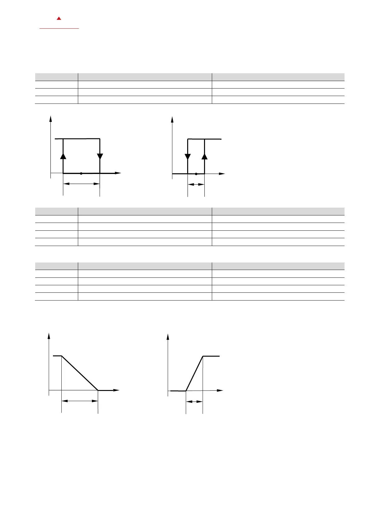
5.8.4 On/Off control
The diagrams show the on/off control sequence for all applications except 4-pipe heating and cooling (P200 = 4) which is
explained below.
Valid values for given chart
Valid values for given chart
Valid values for given chart
0 or 1 (1 only if P207 = 4)
2 (= 0-10V valve) or 3 (= 2-10V valve)
5.8.7 Graphics for modulating and 3-position control
X
H
Switching span heating
X
C
Switching span cooling
W Set point
X
pH
Proportional band heating
X
pC
Proportional band cooling
W Set point

 Loading...