Doc: 70-00-0958A V1.0, 20221102 © Vector Controls GmbH, Switzerland Page 27-34
Subject to change without notice www.vectorcontrols.com
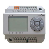
5.8.10 Analog fan control in automatic mode (on/off control)
Note: The analog fan output is proportional to the control loop output. The fan runs indefinitely variable between Low fan
level (P209) and high fan level (P211). 20% low fan level equals to 2V analog output. For a 2-10V fan output, set P209 to
20% and P211 to 100%.
For on/off valves, the fan keeps running at 20% of range as long as the valve is active. When the on/off valve is closed,
the fan returns to low fan level.
The proportional band is adjusted for on/off control as follows:
For the remaining X
H
/ X
C
: X
fanH =
X
H
*2+1 and X
fanC =
X
C
* 2+1
5.8.11 Analog fan control for modulating and 3-position valve
With modulating and 3-position valve, the fan output is proportional to the control loop output. The fan runs indefinitely
variable between Low fan level (P209) and high fan level (P211). 20% low fan level equals to 2V analog output.
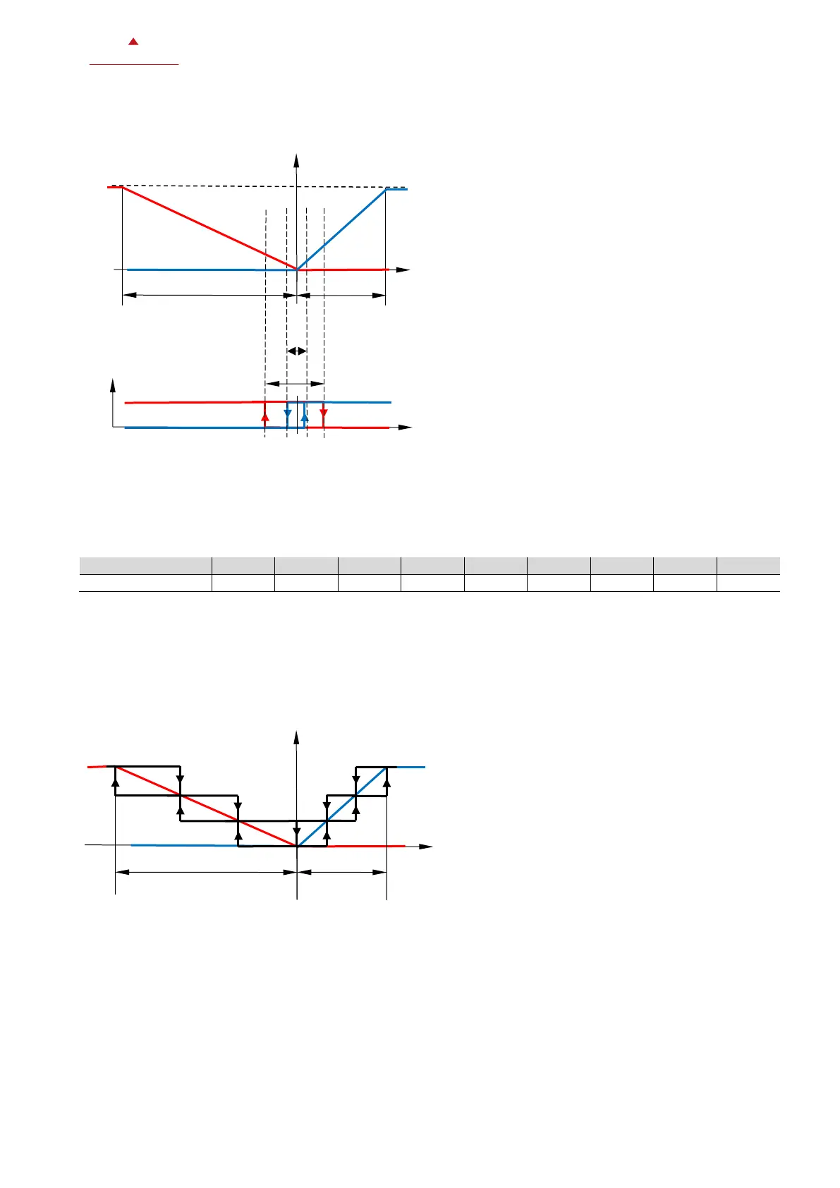
5.8.12 3-stage fan control in automatic mode (Modulating valve)
Note:
• Fan is turned off when the valve is fully closed
• This chart shows the fan control for 2-pipe and 4-pipe heating or cooling applications (P200 = 0 to 5).
For 4-pipe heating and cooling application (P200 = 6), the dead zone between heating and cooling switch point is
not depicted.
• This chart assumes P213 (Minimum fan speed in auto mode) is set to 0 = Fan off (default).
W Set point
X
H
Switching span heating
X
C
Switching span cooling
X
fanH
Switching span for fan heating
X
fanC
Switching span for fan cooling
DO4/DO5 (Valve or heater)
X
pH
Proportional band heating
X
pC
Proportional band cooling
W Set point

 Loading...