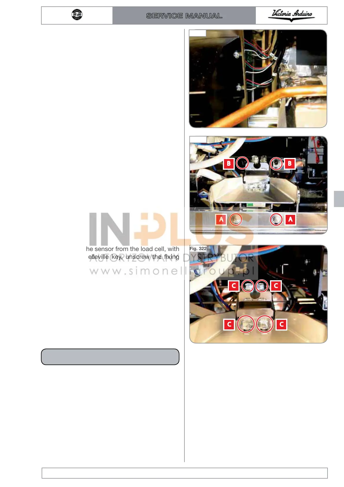
3 Disconnect the electrical wiring of the group
examined 1,2 and 3 from the control unit.
4 With a Phillips screwdriver, unscrew the two
front screws "A" and loosen the rear screws
"B".
At this point the load cell is free and can be
pulled towards the front of the machine.
5 To remove the sensor from the load cell, with
a No., 10 Belleville key, unscrew the fixing
screws "C".
Edition 01 of 08/2017
8.21
SERVICE MANUAL
Fig. 320
Fig. 321
Fig. 322
The maximum weight supported by each sen-
sor is 3 kg.
WARNING

 Loading...