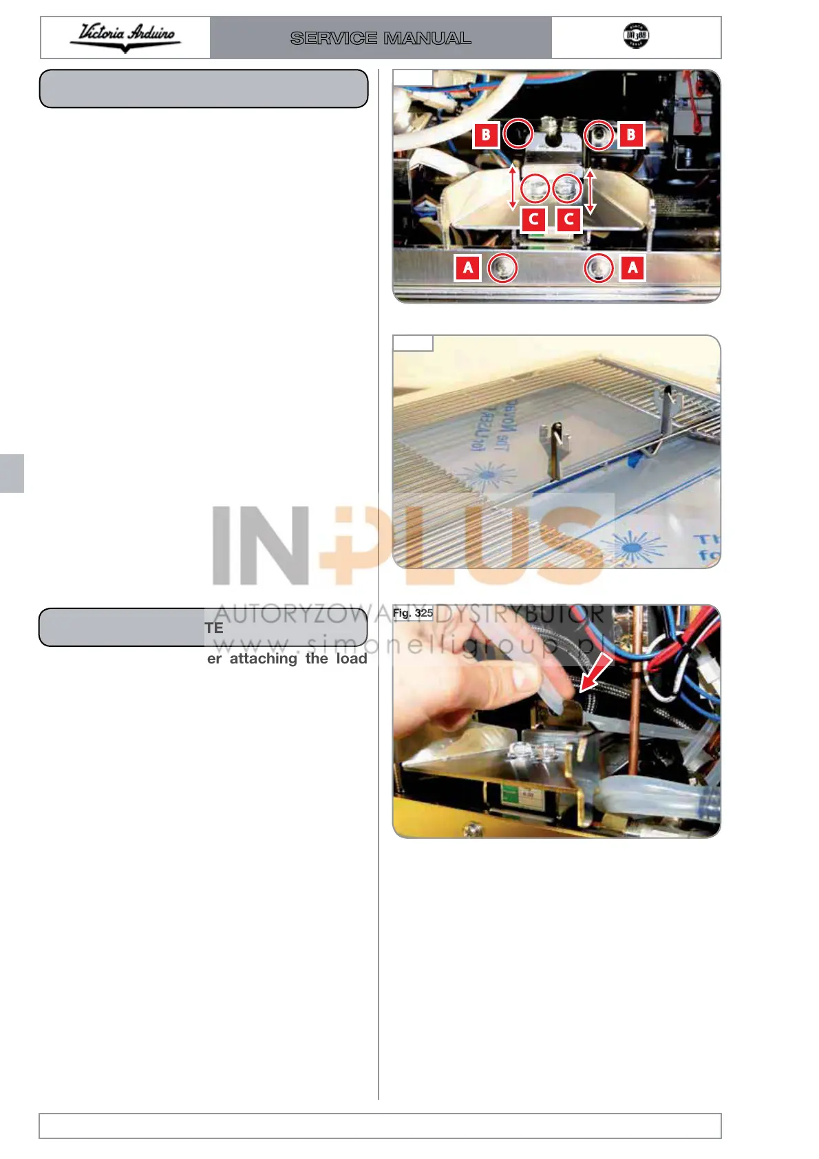
During reassembly, after attaching the load
cell, be sure to insert the drain hose in its
seat. This operation is essential for groups 1
and 2, while not affecting the 3 group.
NOTE
The correct position of the load cell is obtained
by matching the front panel with the beginning of
the descent of the hook of the cup holder grid.
Edition 01 of 08/2017
8.22
SERVICE MANUAL
Fig. 323
During reassembly it is necessary to adjust the
inclination of the sensor via the two front screws
"A" and the rear screws "B":
A: The front screws must be secured in the
rear upper part of the slot.
B: The rear screws must be fixed at the bottom
part of the slot.
Furthermore, it is necessary to adjust the longitu-
dinal position of the load cell with respect to the
front panel.
NOTE
Fig. 325
Fig. 324

 Loading...