Brakes 275
Brake System Controls
The air compressor, governor, pressure reg-
ulator valve and reservoirs are control
devices. Their function is to build up,
maintain and control air pressure in the
reservoirs. This is so that pressure is held
constant between the minimum and maxi-
mum range established for air brake
operation.
The brake valve, quick release valve, brake
chambers and slack adjusters are applica-
tion devices. They distribute the air
pressure and convert its energy into the me-
chanical force necessary to apply or release
the brakes.
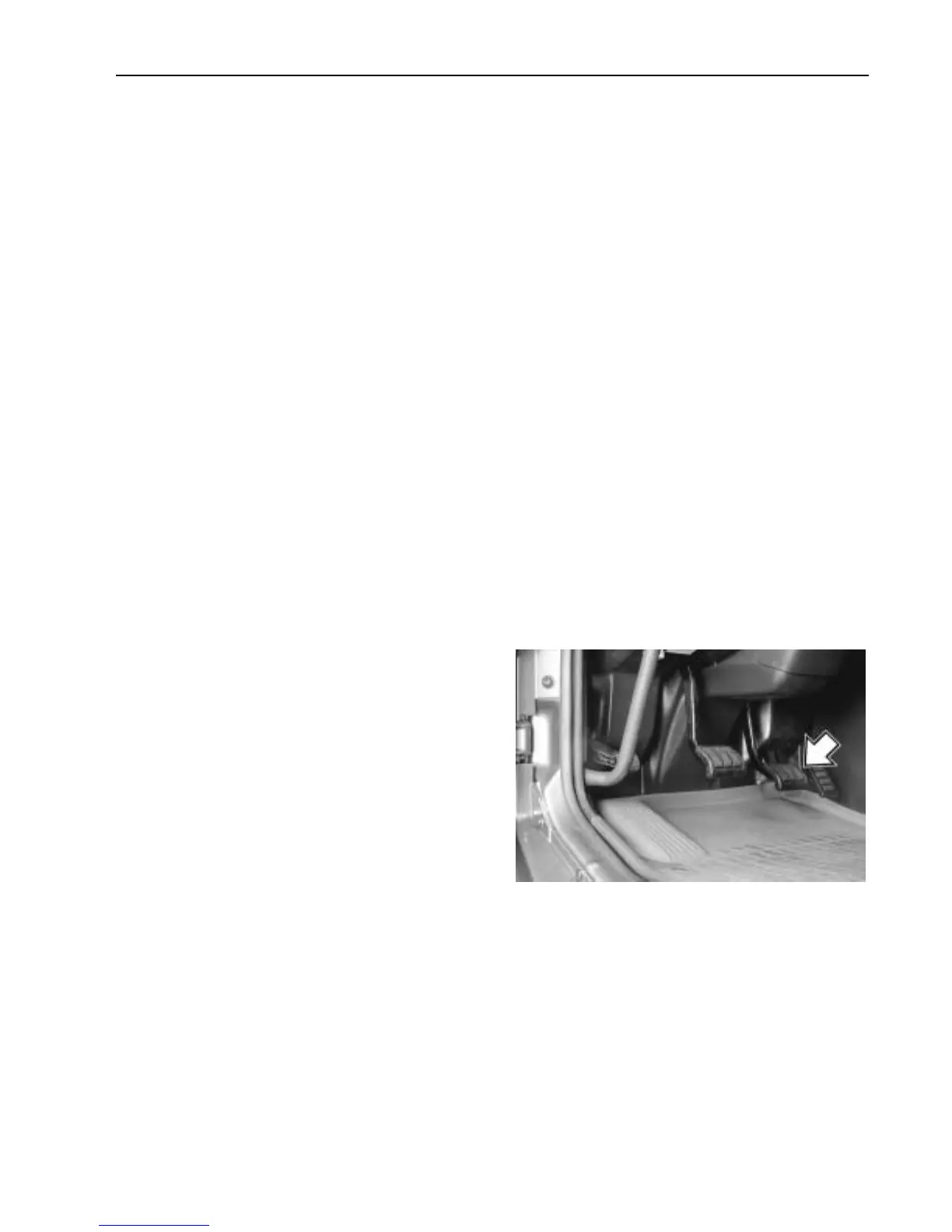
Foot Brake Valve
The foot brake valve is directly connected
to the brake pedal. The valve gives a pro-
gressive output against the pedal travel.
This allows better control of the pressure in
the first half of the pedal travel. In the last
half of the pedal travel, the pressure output
increase is faster.
The foot brake valve applies the service
brakes, incorporating both the primary and
secondary air systems. The primary system
controls the rear brakes and the secondary
system controls the front brakes. The foot
brake valve receives air from the com-
pressed air tanks. Air pressure is then
delivered to the wheel brake chambers as
required by the amount of pressure exerted
on the foot brake pedal. The brake chamber
force then applies the wheel brakes.
W5000920
 Loading...