January 2001/ version 1.4
WMOi3 Integrated Modem
confidential ©
19/61
This document is the sole and exclusive property of WAVECOM. Not to be distributed or divulged
without prior written agreement. Ce document est la propriété exlcusive de WAVECOM. Il ne peut
être communiqué ou divulgué à des tiers sans son autorisation préalable.
4 Hardware Interfaces
This chapter describes the hardware interfaces:
• interfaces on the 50-pin general purpose connector
• RF interface
• SIM interface
4.1 Interfaces on the 50-pin general purpose connector
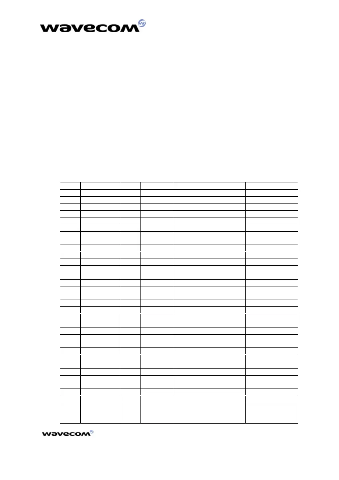
4.1.1 The 50-pin connector description
Table 2 : 50-pin connector description
Pin # Name I/O I/O type Description Comment
1 GND GROUND High current
2 GND GROUND High current
3 +5V Supply High current
4 +5V Supply High current
5 CT109/DCD O CMOS/2X RS232-Data Carrier Detect
6 GND GROUND High current
7
GPIO4 I/O CMOS/2X General Purpose I/O
8 SPK2N O Analog Speaker2 negative output
9 CT125/RI O CMOS/2X RS232-Ring Indicator
10 SPK2P O Analog Speaker 2 positive output
11 Flashing LED I/O CMOS/2X Working mode indication
Led
Driven by module
12 SPK1P O Analog Speaker 1 positive output
13 CT106/CTS O 1X RS232 interface Clear To
Send
14 SPK1N O Analog Speaker 1 negative output
15 ON/~OFF I Power ON/OFF control ON = VCC
(3)
16 MIC2P I Analog Microphone 2 positive
input
17 AUXV0 I Analog Auxiliary ADC input
18 MIC2N I Analog Microphone 2 negative
input
19 ~RST I Reset active low Open Collector
20 MIC1P I Analog Microphone 1 positive
input
21 GND I Ground
22 MIC1N I Analog Microphone 1 negative
input
23 BOOT I BOOT Open Collector
24 GND GROUND High current
25 CT103/TX I RS232 interface - Transmit Pull up to VCC
with 100KΩ when
not used
 Loading...