January 2001/ version 1.4
WMOi3 Integrated Modem
confidential ©
30/61
This document is the sole and exclusive property of WAVECOM. Not to be distributed or divulged
without prior written agreement. Ce document est la propriété exlcusive de WAVECOM. Il ne peut
être communiqué ou divulgué à des tiers sans son autorisation préalable.
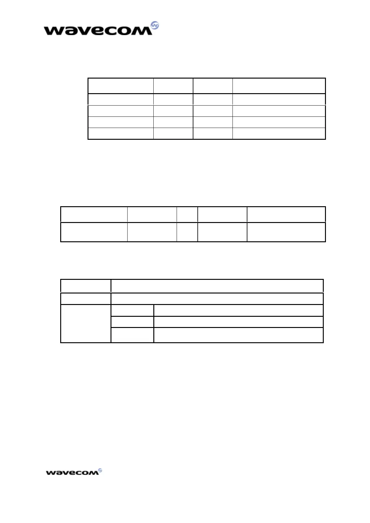
Table 12 : reset signal operating conditions
Parameter Min Max Condition
*V
T-
1.1V 1.2 V
*V
T+
1.7V 1.9 V
V
OL
0.4 V I
OL
= -50 µA
V
OH
2.0 V I
OH
= 50 µA
V
T-,
V
T+ :
Hysterisis Level
4.1.7 Flashing LED
The flashing LED signal is used to indicate the working mode of the WMOi3.
Table 13 : the flashing LED pin description
Signal Pin number I/O I/O type* Description
Flashing LED 11 I/O CMOS/2X Working mode indication
LED
*See Table 3 “operating conditions” in subdivision 4.1.1The 50-pin
connector description
Table 14 : LED and WMOi3 status
LED statusLED status WMOi3 statusWMOi3 status
OFFOFF Download mode or switched OFF
Permanent Switched ON, not registered on the network
Slow flash Switched ON, registered on the network
ONON
Quick flash Switched ON, registered on the network,
communication in progress
 Loading...