January 2001/ version 1.4
WMOi3 Integrated Modem
confidential ©
23/61
This document is the sole and exclusive property of WAVECOM. Not to be distributed or divulged
without prior written agreement. Ce document est la propriété exlcusive de WAVECOM. Il ne peut
être communiqué ou divulgué à des tiers sans son autorisation préalable.
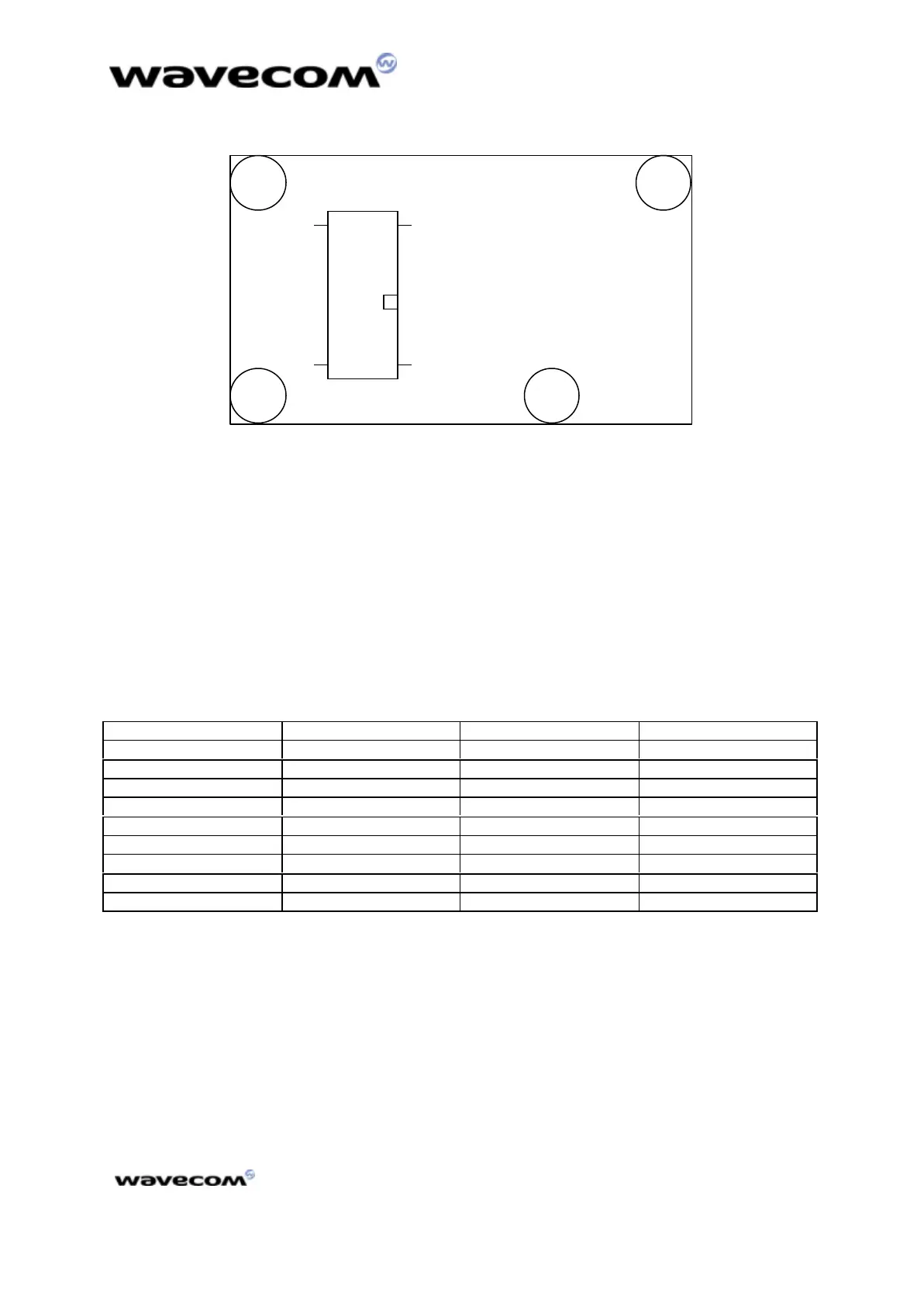
49 50
1 2
figure 4 : pin numbering/bottom view
4.1.2 Power supply
The main power supply is provided through a double connection. These
connections are respectively the pin 3 and 4 for the +5V and the pins 1 and 2 for
the ground (GND). The pins 6, 21, 24 and 40 are also ground connection in order
to produce a proper ground plane.
A 5V +/-5% - 1A power is strictly required to supply the modem. Otherwise,
serious dysfunctions may appear. However, the modem does not have to
constantly deliver 1A current at 5V on this power supply.
This power supply is internally regulated to a nominal value VBATT.
Table 4 : power supply pin description
Pin numberPin number NameName DescriptionDescription CommentComment
1 GND Ground High Current
2 GND Ground High Current
3 +5 V Ground High Current
4 +5 V Ground High Current
6 GND Ground High Current
21 GND Ground High Current
24 GND Ground High Current
41* GND Ground High Current
50* GND Ground High Current
*for engineering sample
 Loading...