January 2001/ version 1.4
WMOi3 Integrated Modem
confidential ©
39/61
This document is the sole and exclusive property of WAVECOM. Not to be distributed or divulged
without prior written agreement. Ce document est la propriété exlcusive de WAVECOM. Il ne peut
être communiqué ou divulgué à des tiers sans son autorisation préalable.
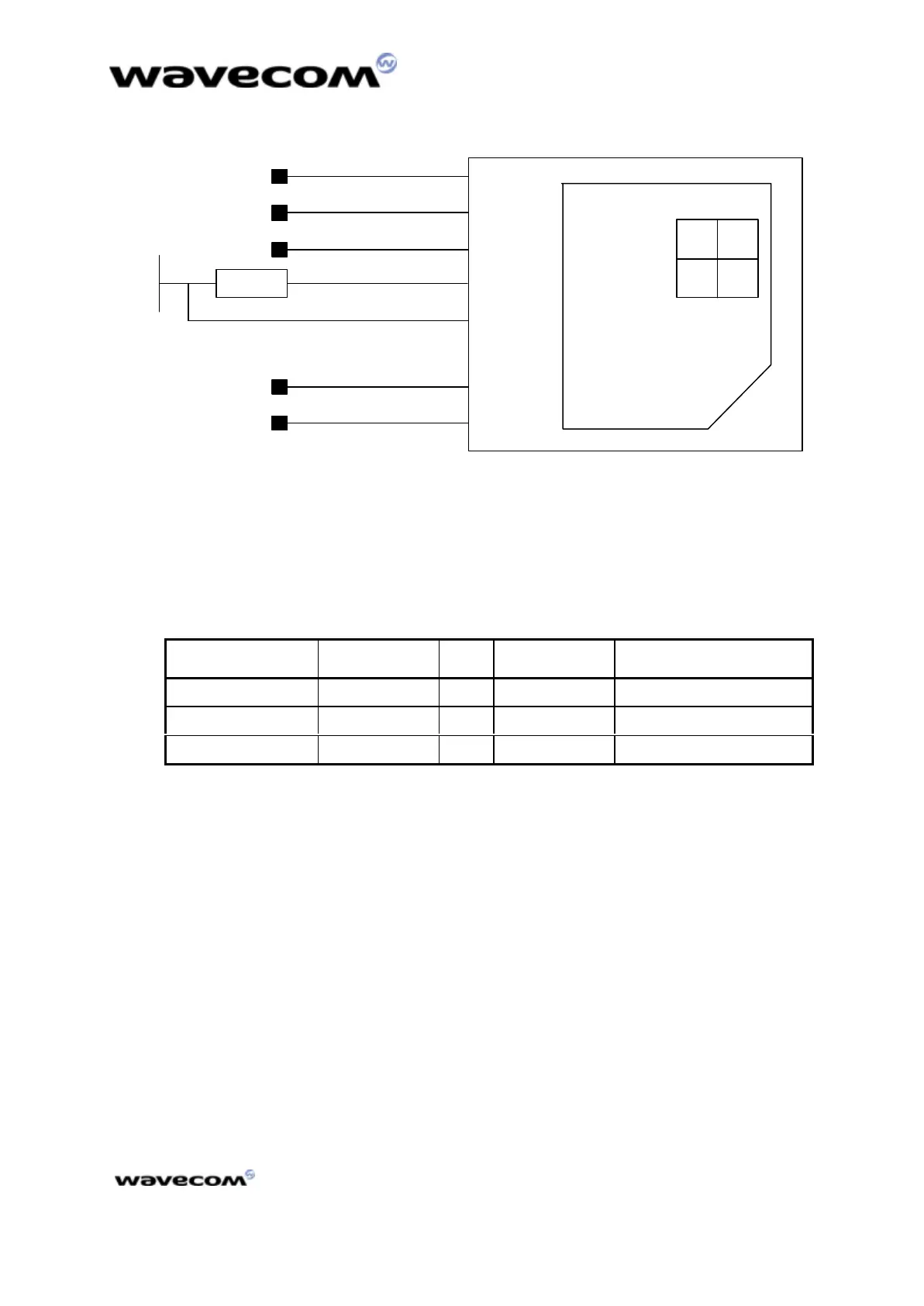
Figure Figure 1414: : SIM socket
4.1.12 SPI bus
The SPI bus includes a CLK signal, an I/O signal and an EN signal complying with
SPI bus standard. The maximum speed transfer is 3.25Mb/s.
Table 25 : SPI Bus pin description
Signal Pin number I/O I/O type* Description
SPI_CLK 44 O 1X SPI Serial Clock
SPI_IO 43 I/O CMOS / 1X SPI Data
SPI_EN 42 O 1X SPI Enable
*See Table 3 “operating conditions” in subdivision 4.1.1The 50-pin
connector description
4.1.13 Keypad interface
This interface provides 10 connections : 5 rows (R0 to R4) and 5 columns (C0 to
C4).
The scanning is a digital one, and the debouncing is done in the integrated
modem. No discrete components like R,C (Resistor, Capacitor) are needed.
It is possible to scan the column and rows using the: AT+ CMER. command. See
AT command user’s guide for more details.
 Loading...