Programming Fresh-Air
16
5.3 Cycle Determination
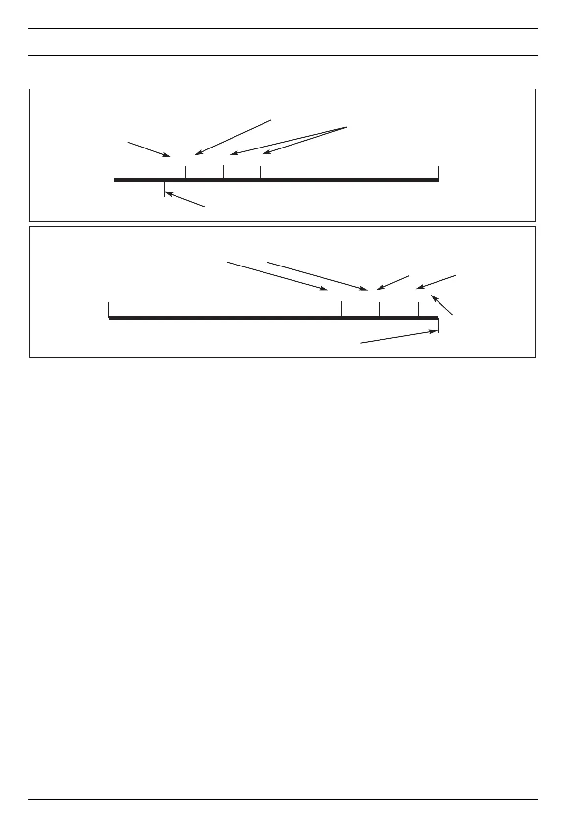
Here-above drawings explain the operating window with
the associated setpoints and reheat differentials.
The choice between heat cycle and cool cycle is done auto-
matically by the controller card depending on the chilled
water temperature as recorded by the controller card. The
switching temperature is determines by the programming
lines 3 and 4 (snow key).
Factory settings are as following:
Lower ceiling : 18 °C
Higher ceiling : 20 °C
This means that below 18 °C chilled water temperature the
fresh-air controller considers that cool cycle operation is re-
quired; above 20 °C the controller switches to heat cycle op-
eration. Between 18 °C and 20 °C the controllers suspends
controlling activity and waits to see which cycle is definitely
adopted.
5.4 Blower Speed Regulation
As already explained blower speed can be set in a differen-
tial way between the Fresh-Air blowers (1b) and the Extrac-
tion Blowers (2b).
In addition the Fresh-Air blowers can be set manually on a
fixed speed without any reference to the chilled water tem-
perature and/or outside/inside air temperatures or start-up
procedure. This choice can be made in programming mode
(sun key - line 9).
5.5 Access Code
The end-user can deny access to all program settings by in-
troducing an access code (see 5.7.3 "Programming through
Snow Key" - code <b>). Blower speed and setpoints always
remain accessible.
Once an access code is validated, the digital panel will show
<Code> if the end-user tries to access other functions then
blower speed or set-point. To gain full access push the sun
key to reach the code number as programmed and push the
<F> key again to gain access to full program settings.
5.6 Visual Error Codes - Digital Display
The following malfunctions will be displayed directly on the
digital display by a code and will be followed by a system
halt.
Whenever any of these codes appear the system is stopped
for approx. 60 seconds and then a re-start is attempted.
If for more than 30 minutes the same malfunction occurs,
the system will be stopped completely and the error-code
will become steady.
No more re-starts will be attempted and the user will have
to re-set the system by pushing the ON/OFF switch or by
temporarily cutting out the AC supply to the system.
35°C
24°C
22°C
20°C
5°C
24°C
22°C
21.5°C
Reference Setpoint
Example of operating window setting - Fresh-Air Control - Cool Cycle
Reheat 2 cuts in at 20° - cuts out at 22°
Cooling Coil 3 way valve cuts out at 20°
and cuts in again at 22°
Reheat 1 cuts in at 22° - cuts out at 24°
Reference Setpoint Ceiling Limit = 20° - i.e. reference setpoint will always be 20 °C or higher
Outside air temperature
Differential = 16 °C - Prog. Line 0 - Sun Key
Outside air temperature
Differential = 18 °C - Prog. Line 2 - Sun Key
Reference Setpoint Ceiling Limit = 24° - i.e. reference setpoint will always be 24 °C or lower
Reference Setpoint
Reheat 1 cuts out at 24° - cuts in at 22°
Heating Coil 3 way valve cuts out at 24°
and cuts in again at 22°
Reheat 2 cuts out at 22° - cuts in at 21.5°
Example of operating window setting - Fresh-Air Control - Heat Cycle
 Loading...