コンパネ Ass'y 部
※シートを取り外す時に、ステイでコンパネAss'yを45度
程度に固定した状態で作業がしにくい場合は、180度開
いて作業をしてください。
10. ADA シート(所要時間:約 6 分)
10-1. コンパネ Ass'y を固定します。(1 項参照)
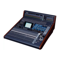
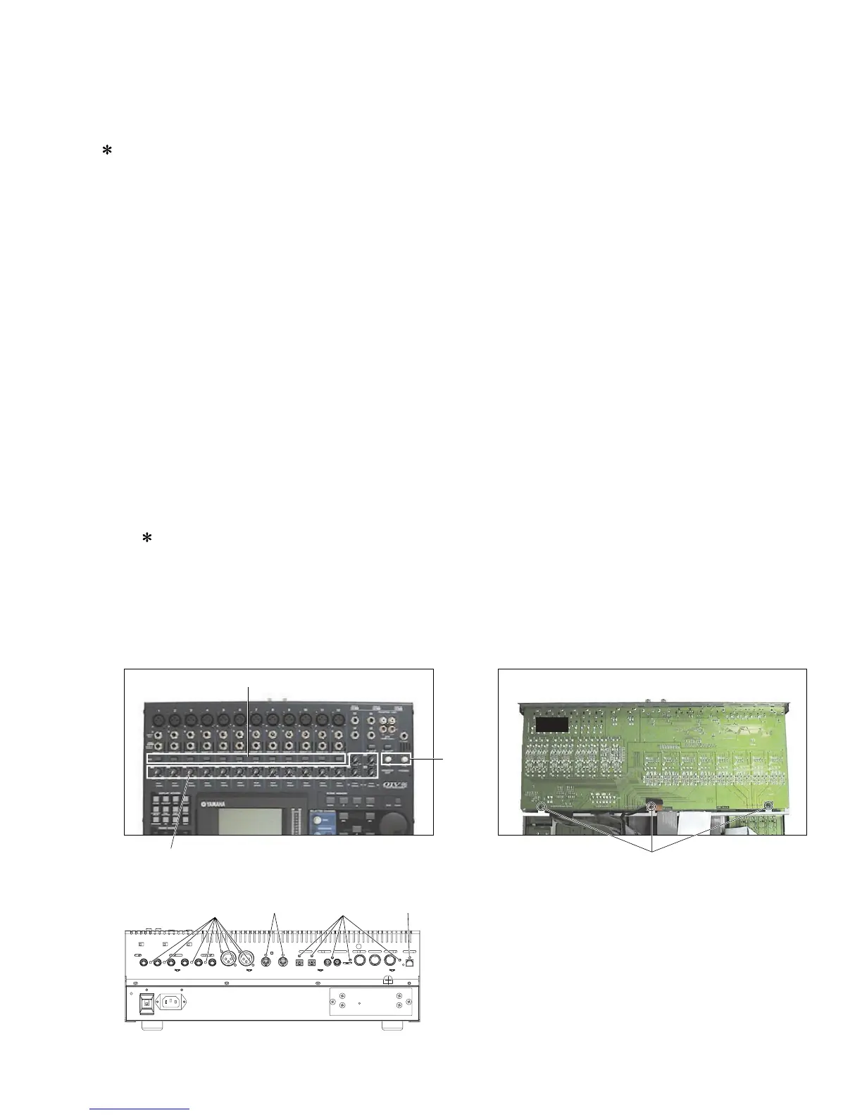
10-2. [300]のネジ3本と[310]のネジ13本、[320]のネジ3本
を外して、ADAシートを外します。(図3、写真 10)
11. HA シート(所要時間:約 15 分)
11-1. コントロールパネル面より、[280]の特殊六角ナット
29 個を外します。(写真 11)
11-2. コンパネ Ass'y を固定します。(1 項参照)
11-3. ADA シートを外します。(10 項参照)
11-4. [260]のネジ 5 本と[270]のネジ 25 本を外して、HA
シートを外します。(写真 11,12)
11-5. HA シートからノブを 18 個を外します。(写真 9)
※キャノンコネクタ12個とホーンコネクタ12個を
交換する場合は、HA シートに 8ヶ所で半田付け
されているフォーンキャノンシールドを外しま
す。(写真 13,14)
[300]: Bind Head Tapping Screw-B
3.0X8 MFZN2BL (EP600190)
[310]: Bonding Tapping Screw-B
3.0X8 MFZN2BL (VN413300)
[320]: Bonding Screw
3.0X8 MFZN2BL (VP157800)
Control Panel Assembly Section
When removing the circuit board, if it is hard to handle
while the control panel assembly is fixed slantwise
at the stay, open it widely at 180° for the work.
10. ADA Circuit Board
(Time required: About 6 minutes)
10-1. Fasten the control panel assembly. (See procedure 1.)
10-2. Remove the three (3) screws marked [300], the
thirteen (13) screws marked [310] and the three (3)
screws marked [320]. The ADA circuit board can then
be removed. (Fig.3, Photo.10)
11. HA Circuit Board
(Time required: About 15 minutes)
11-1. Remove the twenty-nine (29) hexagonal nuts marked
[280] from the control panel side. (Photo.11)
11-2. Fasten the control panel assembly. (See procedure 1.)
11-3. Remove the ADA circuit board. (See procedure 10.)
11-4. Remove the five (5) screws marked [260] and the
twenty-five (25) screws marked [270]. The HA circuit
board can then be removed. (Photo.11, 12)
11-5. Remove the eighteen (18) knobs from the HA circuit
board. (Photo.9)
When you replace the twelve (12) cannon
connectors and the twelve (12) phone jacks,
remove the phone cannon shield soldered to
the HA circuit board by eight (8) places.
(Photo.13, 14)
Photo.9 (写真9)
(+バインド B タイト)
(ボンディング B タイト)
(ボンディング小ネジ)
Fig. 3 (図3)
Photo.10 (写真10)

 Loading...