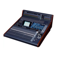
Fader knob
(フェーダーノブ)
<Top view>
<Bottom view>
FD
13. LCD Circuit Board and LCD
(Time required: About 20 minutes)
13-1. Fasten the control panel assembly. (See procedure 1.)
13-2. Remove the ADA circuit board. (See procedure 10.)
13-3. Remove the HA circuit board. (See procedure 11.)
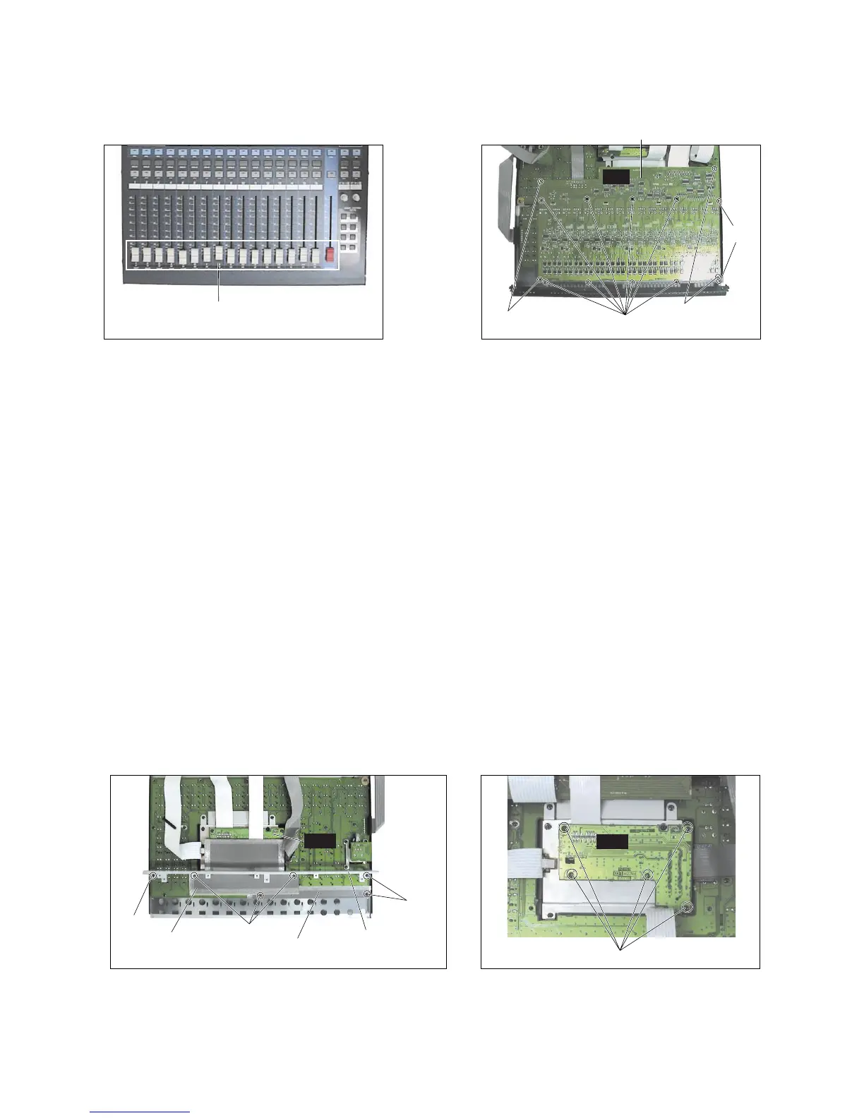
13-4. Remove the six (6) screws marked [190A]. The HA-
ADA angle, PN1 shield plate 1 and 2 can then be
removed. (Photo.17)
13-5. Remove the five (5) screws marked [80]. The LCD
circuit board can then be removed. (Photo.18)
13-6. Remove the two (2) screws marked [100] and the
two (2) screws marked [190B]. The LCD shield plate
can then be removed. (Photo.19)
13-7. Remove the four (4) screws marked [60]. The LCD
can then be removed. (Photo.20)
[210]: Bind Head Tapping Screw-B
3.0X8 MFZN2BL (EP600190)
(+バインド B タイト)
Photo.15 (写真15)
Photo.16 (写真16)
13. LCD シート、液晶ディスプレイ
(所要時間:約 20 分)
13-1. コンパネ Ass'y を固定します。(1 項参照)
13-2. ADA シートを外します。(10 項参照)
13-3. HA シートを外します。(11 項参照)
13-4. [190A]のネジ 6 本を外して、HA-ADA 金具と PN1
シールド板 1、2 を外します。(写真 17)
13-5. [80]のネジ 5 本を外して、LCD シートを外します。
(写真 18)
13-6. [100]のネジ2本と[190B]のネジ2本を外して、LCD
シールド板を外します。(写真 19)
13-7. [60]のネジ4 本を外して、液晶ディスプレイを外し
ます。(写真 20)

 Loading...