77
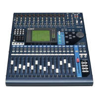
01V96
c. Press the DISPLAY ACCESS [PAIR/GROUP] key a
few times, switch to the OUT FADER GROUP fixed
screen, and press the [SEL 1]~[SEL 16] and [SEL
STEREO] keys and group the 17 faders.
w Group inspection
a. Operate the stereo master fader, repeat the delay
(about 3 seconds/100 mm) twice and repeat the
advance (about 1 second/100 mm) twice.
b. Operate the Channel 1 fader, repeat the delay (about
3 seconds/100 mm) twice and repeat the advance
(about 1 second/100 mm) twice.
c. Check that there are no vibrating faders or extremely
late faders in the above operations
e Recall inspection
a. Press the LAYER [1-16] key and select Layers 1-16.
b. Press the DISPLAY ACCESS [SCENE] key to switch
to the SCENE MEMORY screen, then press the
SCENE MEMORY [
] key or [ ] key to select 0,
then press the [RECALL] key to recall 0.
c. Move all the faders all the way up, press the SCENE
MEMORY [
] key or [ ] key to select 1, then press
the [STORE] key and when the TITLE EDIT screen
is displayed, then select OK to store 1.
d. With the operation method in b., repeat two times
from the 0 recall to the 1 recall.
e. Check that there are no vibrating faders or extremely
late faders in the above operations.
2. ANALOG IN/OUT WORD CLOCK INT
96 kHz inspection
2-1. STEREO OUT L/R
Parameter Must be input from CH1(XLR).
q Gain (both L/R)
w f characteristic (both L/R)
Parameter The permitted range uses 1 kHz as
the reference.
e Residual noise (both L/R)
Parameter Switch STEREO OUT Off.
r L/R level difference
The range for the difference in the gain measured
with q is regulated as follows.
Input frequency
Input level
Regulated output level
Permitted range
1kHz +4dBu +4dBu +4
±
2dBu
t Crosstalk between left and right
Parameter PAN L swung to cut off.
The right side must be the same.
y Maximum output (both L/R)
2-2. 2TR OUT L/R
Parameter Must be input from CH1(XLR).
q Gain (both L/R)
w f characteristic (both L/R)
Parameter The permitted range uses 1 kHz as
the reference.
2-3. OMNI OUT 1~4
Parameters Must be input from CH1 (XLR).
BUS 1~4 ON with CH1 routing.
Assign Bus nCH to OMNI nCH with
an OUT PATCH.
BUS 1-4 MASTER FADER ON.
q Gain (OMNI OUT 1~4)
w f characteristic (OMNI OUT 1~4)
Parameter The permitted range uses 1 kHz as
the reference.
e Residual noise (OMNI OUT 1~4)
Parameter Switch the BUS OUT Off.
r OMNI OUT 1-4 level difference
The range for the difference in the gain measured
with q is regulated as follows.
Input frequency
Input level Permitted range
20Hz +4dBu -1.5~+0.5dB
40kHz +4dBu -1.5~+0.5dB
Permitted range
-86dBu or below
Input frequency Permissible range
Permissible range (distortion ratio)
1kHz +24
±
0.5dBu 0.01% or below
Input frequency
Output level (L)
Permitted range (R)
1kHz +22dBu -58dBu or below
Input frequency
Input level
Regulated output level
Permitted range
1kHz +4dBu -10dBV -10
±
2dBV
Input frequency Input level Permitted range
20Hz +4dBu -1.5~+0.5dB
40kHz +4dBu -1.5~+0.5dB
Input frequency
Input level
Regulated output level
Permitted range
1kHz +4dBu +4dBu +4
±
2dBu
Input frequency
Input level Permitted range
20Hz +4dBu -1.5~+0.5dB
40kHz +4dBu -1.5~+0.5dB
Permitted range
-86dBu or below
Permitted range
Within 1dB
Permitted range
Within 1dB

 Loading...