01V96
92
1-11. 2TR IN/OUT (DIO) test
Contents: Use the DSP SIO and check 2TR OUT
DIGITAL → 2TR IN DIGITAL.
Preparation: Connect the 2TR IN DIGITAL to the 2TR
OUT DIGITAL of the unit with a cable.
Example of execution screen
1-12. ADAT test
Contents: Use the ATSC2 and check ADAT OUT →
ADAT IN.
Preparation: Connect the ADAT IN to the ADAT OUT
of the unit with a cable.
Example of execution screen
1-13. WORD CLOCK test
Contents: WORD CLOCK OUT → IN is counted by
PLLP2 and automatically checked (Fs =
44.1/48/88.2/96 kHz). For the PLL LOCK
check, Read the UNLOCK signal and
check when the clock is stable after the
FS change (after about 200 ms).
To confirm the UnLock, disconnect the
cable connected to WORD CLOCK IN
and check.
Preparation: Connect the IN to the WORD CLOCK
OUT of the unit with the BNC cable.
Example of execution screen
Explanation of display when DSP6 and DSP7 are common
or NG
1-6. MIDI test
Contents: Send/Receive the character string
“SCI2:TEST¥n” (¥n = 0Ah) from/to MIDI
OUT → MIDI IN at 31.25 Kbps and check
that the sent and received strings are
identical.
Preparation: Connect the MIDI IN connector to the
MIDI OUT of the unit with a MIDI cable.
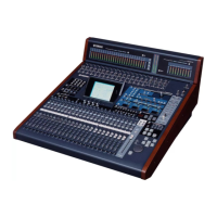
Example of execution screen
EXIT ([DEC] Key->[ENTER] Key)
--- MIDI Loopback ---
OK MIDI Check
OK: SCI2
1) CPU Interface (Data Bus)
...
NG: IC201
0000 0000 XXXX 0000 0000 0000 0000 X00X
MSB X=Error bit LSB
2) SIO Connection (DSP7 -> DSP6)
...
NG: 1 IC201 S0[xx] -> IC301 SI[xx]
IC number
EXIT ([DEC] Key->[ENTER] Key)
--- ADAT ---
OK ADAT OUT->IN
OK: ADAT
EXIT ([DEC] Key->[ENTER] Key)
--- 2TR IN/OUT ---
OK
FS
OK OUT-->IN
OK DIR Lock (RERR)
OK DIT,DIR CDIN, CDOUT
NG:
DIO_SIO 2TR1 [W:12485100 -> R:00000000]
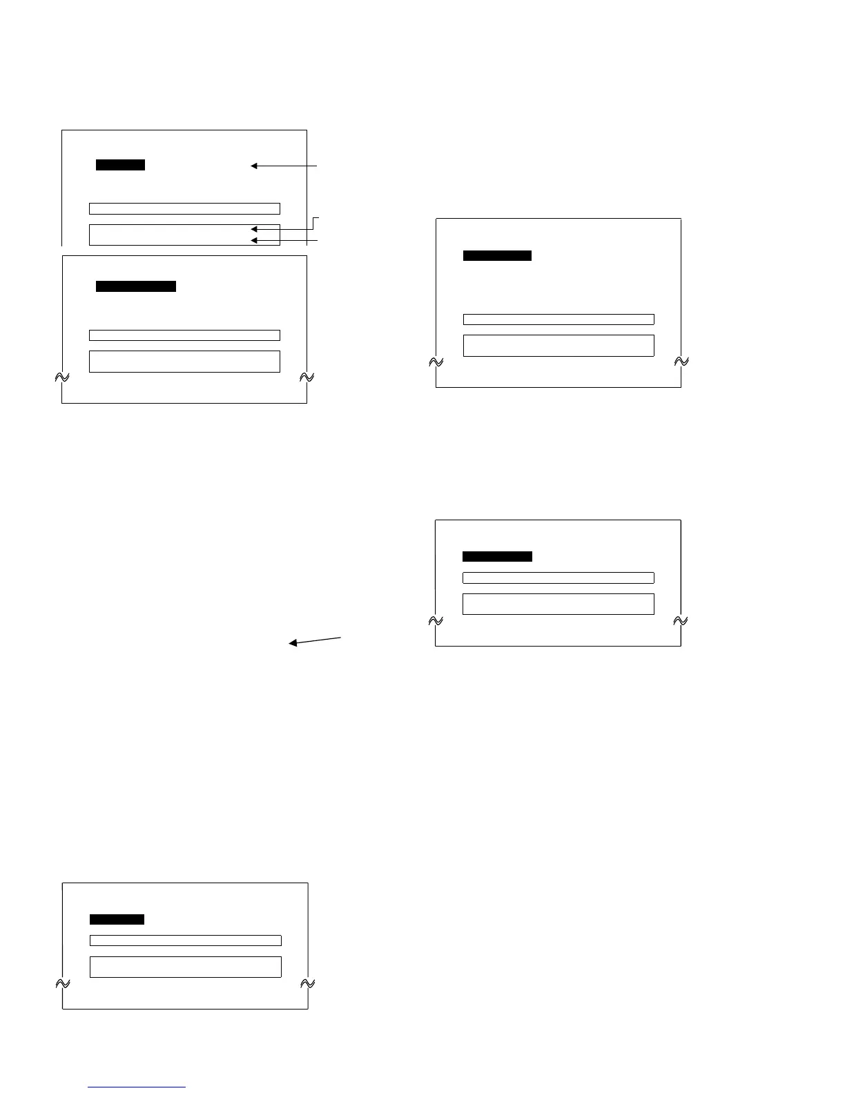
Details are displayed
when NG is determined.
When there are many
NG items, the display
stops after about 20 items.
OKDSP6,SIO
OKDSP7,SIO,ATSC2
---DSP6---
1:CPUInterface(Databus)
NG:TxBusy
1:CPUInterface(Databus)
NG:BIF#010000XXXX0000・・・
---DSP7---
EXIT([DEC]Key->[ENTER]Key)
All items are selected
automatically and cannot
be selected manually.
Items are displayed one
after another after “1:”
during execution.
DSP6 test items DSP7 test items
1: CPU Interface (Data bus) 1: CPU Interface (Data Bus)
2: CPU Interface (Data bus) 2: CPU Interface (Chip Select)
3:
CPU Interface (Chip Select, TXB)
3:
CPU Interface (Address Bus)
4:
CPU Interface (Address bus)
4: E-RAM Interface (Data Bus)
5:
CPU Interface (BUS W/R Reg.)
5:
E-RAM Interface (Address Bus)
6:
DRAM Interface (Data Bus)
6:
SIO Connection (DSP7 → DSP6)
7:
DRAM Interface (Address Bus)
7:
SIO Connection (DSP6 → DSP7)
8:
DRAM Interface (Address Bus & MPR)
8:
SIO Connection (DSP7 → DSP7)
9: SIO Connection 9:
SIO Connection (ATSC → DSP7)
(DSP6--->DSP6 SIO test)
A:
SIO Connection (DSP7 → ATSC)
B:
SIO Connection (ATSC → ATSC)

 Loading...