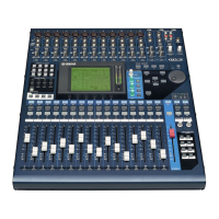
01V96
99
MODE Changing the input/output terminals
ANALOG Patches the ANALOG I/O to the input/output.
SLOT Patches the SLOT I/O to the input/output.
ADAT Patches the ADAT and 2TRD I/O to the input/output.
CLOCK Changing the clock source
INT 44.1k
INT 48k
INT 88.2k
INT 96k
FS Displays the operation clock.
END Exits the Audio Check mode.
INPUT button Sets the INPUT CHANNEL to ON/OFF.
The INPUT route of the last CHANNEL set is displayed.
Multiple CHANNELs are not set to ON at the same time.
The voice of the CHANNEL set to ON is output to the C-R monitor (headphones).
INPUT route display selection
Selects the route display.
INPUT route Displays the outline of the route of the signal selected by the INPUT route display selection.
BUS. AUX buttons Sets the OUTPUT CHANNEL to ON/OFF.
The OUTPUT route of the last CHANNEL set is displayed.
Multiple CHANNELs are not set to ON at the same time.
OUTPUT route display selection
Selects the route display CHANNEL.
OUTPUT route Displays the outline of the route of the signal selected by the OUTPUT route display selection.
3-2. Check contents
Common contents:
1) The IN PORT and OUT PORT are determined by setting the INPUT CH and OUTPUT CH (BUS/AUX).
2) When the INPUT CH setting is S1...S4, the default STxL INPUT route is displayed.
To display the STxR INPUT route, manually change the INPUT route display selection.
Mode: Patch setting during ANALOG
INPUT CH IN PORT OUTPUT CH(BUS/AUX) OUT PORT
CH1 INPUT1 BUS1 OMNI1
CH2 INPUT2 BUS2 OMNI2
CH3 INPUT3 BUS3 OMNI3
CH4 INPUT4 BUS4 OMNI4
CH5 INPUT5 BUS5 -
CH6 INPUT6 BUS6 -
CH7 INPUT7 BUS7 -
CH8 INPUT8 BUS8 -
CH9 INPUT9 AUX1 -
CH10 INPUT10 AUX2 -
CH11 INPUT11 AUX3 -
CH12 INPUT12 AUX4 -
CH13 INPUT13 AUX5 -
CH14 INPUT14 AUX6 -
CH15 INPUT15 AUX7 -
CH16 INPUT16 AUX8 -
CH17 INPUT1

 Loading...