01V96
98
Startup method
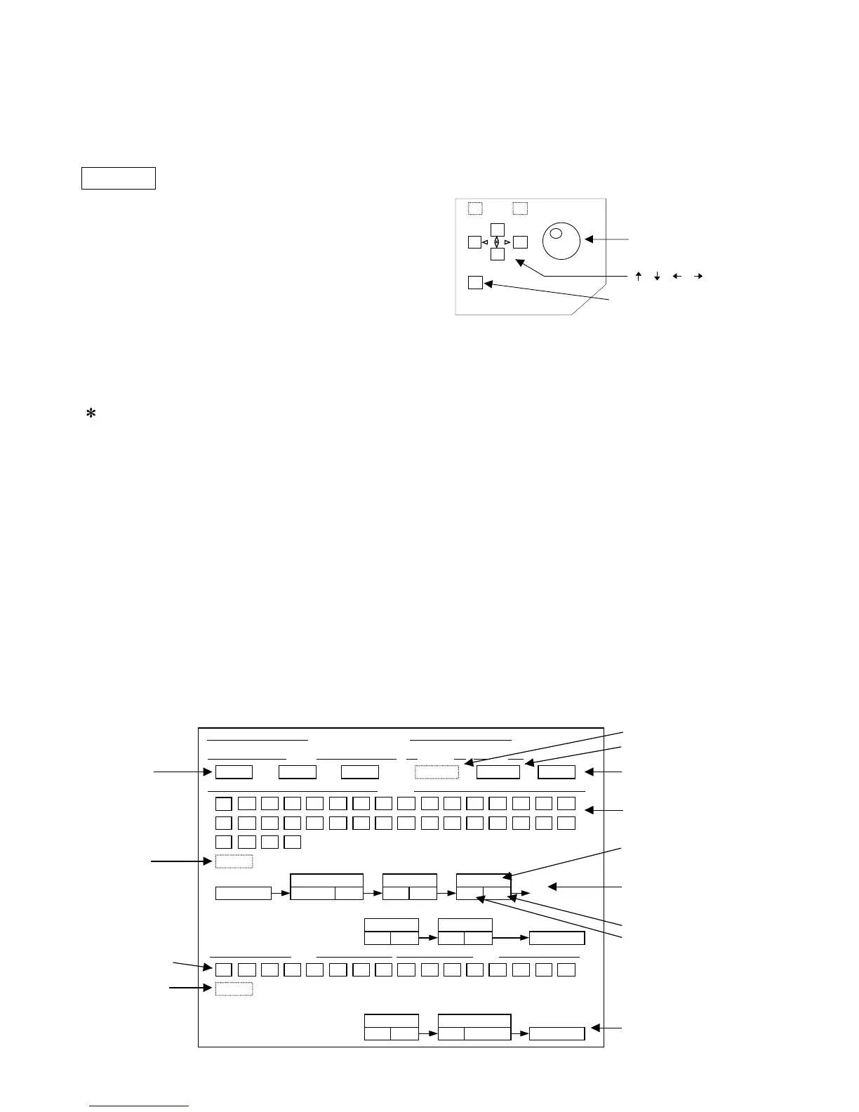
Keys on the panel used for the Audio Check
Startup method
While pressing the [HOME (METER)] and [AUX5]
keys, turn the power ON.
Limits
• Possible operation keys are for the DATA ENTRY
SECTION only.
• Parameters cannot be changed according to
communication.
• LED displayed on the panel is for the STEREO
METER only.
• FADER is not effective.
• Fixed parameters:
• INPUT • BUS/AUX/STEREO OUT are all set to
nominal levels.
• Oscillator is output to all BUS/AUX.
• The output of the Oscillator STEREO is OFF.
• Oscillator waveform is set to 1 kHz.
• Oscillator output is set to –20 dB.
• ST swings the PAN to the left and right. The
others have the PAN centered.
3. Audio Check
CAUTION!
Be sure to press the [END] button to complete
the Audio Check. If the [END] button is not
pressed and the power is turned OFF, the current
memory data of the unit will be erased and the unit
will not return to the condition before the check.
However, if the current memory data: Scene
Memory, Input Patch Library, Output Patch Library,
Surround Monitor Library, and Automix are saved
before starting the Audio Check, this data can be
recovered but other data must be reset.
3-1. Outline
Execute the Audio Check for 01V96.
Check method
Insert the voice signal in the ANALOG, SLOT, and
2TR Digital input, select INPUT CH 1 to 48, and
check the headphone output. If the voice signal
input is not correctly output, the LSI on the selected
signal route is faulty.
Because the built-in oscillator (1 kHz/-20 dB, sine
wave) is output to BUS 1 to 8 and AUX 1 to 8,
select BUS 1 to 8 and AUX 1 to 8 and check
ANALOG, SLOT, and 2TR Digital output set in the
OUT PORT. If the sine wave is not correctly output,
the LSI on the selected signal route is faulty.
[ ], [ ], [ ], [ ] keys:
Used to move the cursor
[ENTER] key:
Used to determine the
selection and ON/OFF
[WHEEL]:
Used for the route display
selection and to move the
cursor of the INPUT ・BUS/
AUX button.
Screen explanation
12345678 91011121314
15
16
12345678 123456
7
8
17 18 19 20
S1 S2 S3 S4
CH1
21 22 23 24 25 26 27 28 29 30
31
32
BUS1
IN PORT
ADC
BUS AUX
DSP7-1
IC103 IC201
16, 17 9 66 135
DSP7-2
IC202
128 135
DSP7-3
IC203
128 129
DSP7-4
IC204
97 129 PHONE
INPUT1
INT 48k INT 48k END
CLOCK FS
(c) YAMAHA2003
MODE
CLOCK
FS
END
INPUT button
IC number
INPUT route
IC input PIN number
IC output PIN number
OUTPUT route
01V96 Audio Check
MODE
ANALOG
SLOT
DSP7-4
IC204
1kHz 130
DAC
OUTPUT
OMNI 1
IC151
6 22, 23
ADAT
INPUT
route display
selection
OUTPUT
BUS, AUX buttons
route display
selection